SECTION 2: LOOSE PARTS
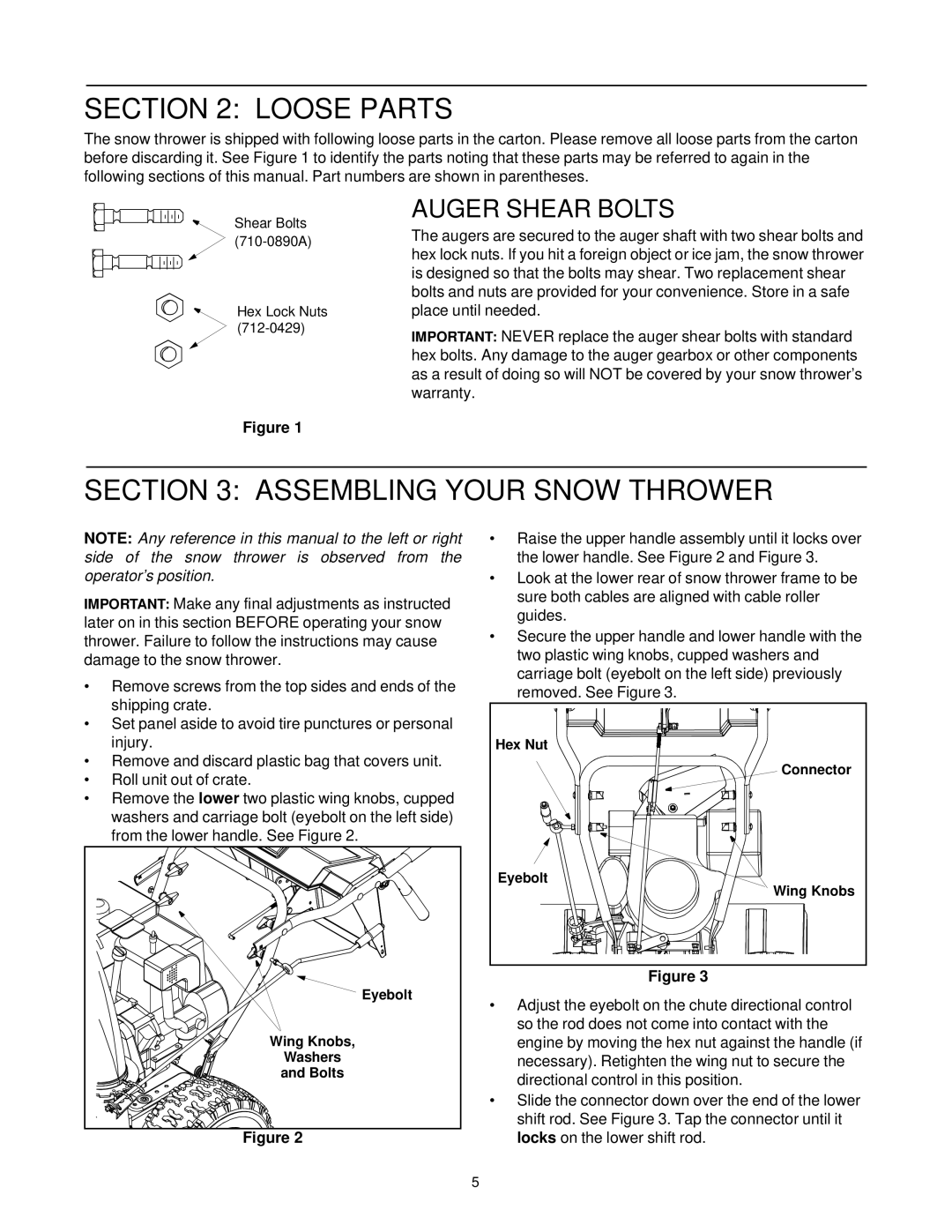
The snow thrower is shipped with following loose parts in the carton. Please remove all loose parts from the carton before discarding it. See Figure 1 to identify the parts noting that these parts may be referred to again in the following sections of this manual. Part numbers are shown in parentheses.
Shear Bolts
Hex Lock Nuts
AUGER SHEAR BOLTS
The augers are secured to the auger shaft with two shear bolts and hex lock nuts. If you hit a foreign object or ice jam, the snow thrower is designed so that the bolts may shear. Two replacement shear bolts and nuts are provided for your convenience. Store in a safe place until needed.
IMPORTANT: NEVER replace the auger shear bolts with standard hex bolts. Any damage to the auger gearbox or other components as a result of doing so will NOT be covered by your snow thrower’s warranty.
Figure 1
SECTION 3: ASSEMBLING YOUR SNOW THROWER
NOTE: Any reference in this manual to the left or right side of the snow thrower is observed from the operator’s position.
IMPORTANT: Make any final adjustments as instructed later on in this section BEFORE operating your snow thrower. Failure to follow the instructions may cause damage to the snow thrower.
•Remove screws from the top sides and ends of the shipping crate.
•Set panel aside to avoid tire punctures or personal injury.
•Remove and discard plastic bag that covers unit.
•Roll unit out of crate.
•Remove the lower two plastic wing knobs, cupped washers and carriage bolt (eyebolt on the left side) from the lower handle. See Figure 2.
Eyebolt |
Wing Knobs, |
Washers |
and Bolts |
Figure 2
•Raise the upper handle assembly until it locks over the lower handle. See Figure 2 and Figure 3.
•Look at the lower rear of snow thrower frame to be sure both cables are aligned with cable roller guides.
•Secure the upper handle and lower handle with the two plastic wing knobs, cupped washers and carriage bolt (eyebolt on the left side) previously removed. See Figure 3.
Hex Nut |
Connector |
Eyebolt |
Wing Knobs |
Figure 3
•Adjust the eyebolt on the chute directional control so the rod does not come into contact with the engine by moving the hex nut against the handle (if necessary). Retighten the wing nut to secure the directional control in this position.
•Slide the connector down over the end of the lower shift rod. See Figure 3. Tap the connector until it locks on the lower shift rod.
5