SECTION 2: ASSEMBLING YOUR SNOW THROWER
Loose Parts
The augers are secured to the auger shaft with two shear bolts and hex lock nuts. If you hit a foreign object or ice jam, the snow thrower is designed so that the bolts may shear. Two replacement shear bolts and nuts are provided for your convenience. Store in a safe place until needed. See Figure 1.
Shear Bolts |
| Hex Lock |
| ||
|
| Nuts |
Figure 1
Assembly
WARNING: Disconnect spark plug wire and ground it against the engine to prevent unintended starting.
NOTE: All references to right or left side of the snow thrower are determined from behind the unit in the operating position. The “operator’s position” is defined as standing directly behind the snow thrower, facing the handle panel.
•Remove the lower two plastic wing knobs, cupped washers and carriage bolt (eyebolt on the left side) from the lower handle. See Figure 2.
Lower | Handle |
Handle | Panel |
| Upper Handle |
| Wing Nuts, |
| Washers, & Bolts |
Figure 2
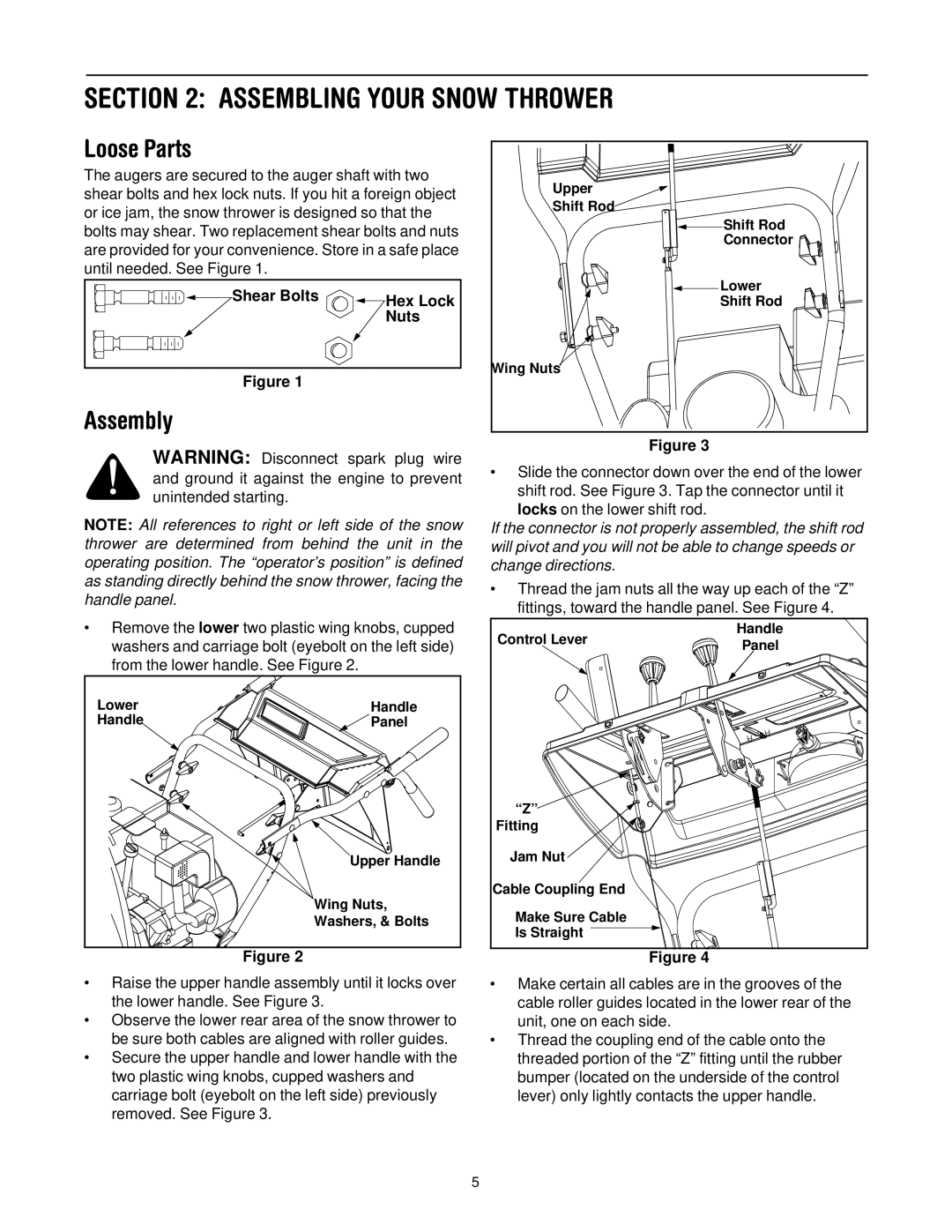
•Raise the upper handle assembly until it locks over the lower handle. See Figure 3.
•Observe the lower rear area of the snow thrower to be sure both cables are aligned with roller guides.
•Secure the upper handle and lower handle with the two plastic wing knobs, cupped washers and carriage bolt (eyebolt on the left side) previously removed. See Figure 3.
Upper |
Shift Rod |
Shift Rod |
Connector |
Lower |
Shift Rod |
Wing Nuts |
Figure 3
•Slide the connector down over the end of the lower shift rod. See Figure 3. Tap the connector until it locks on the lower shift rod.
If the connector is not properly assembled, the shift rod will pivot and you will not be able to change speeds or change directions.
•Thread the jam nuts all the way up each of the “Z” fittings, toward the handle panel. See Figure 4.
Control Lever | Handle | |
Panel | ||
| ||
“Z” |
| |
Fitting |
| |
Jam Nut |
| |
Cable Coupling End |
| |
Make Sure Cable |
| |
Is Straight |
|
Figure 4
•Make certain all cables are in the grooves of the cable roller guides located in the lower rear of the unit, one on each side.
•Thread the coupling end of the cable onto the threaded portion of the “Z” fitting until the rubber bumper (located on the underside of the control lever) only lightly contacts the upper handle.
5