Shift Rod
To adjust the shift rod, proceed as follows.
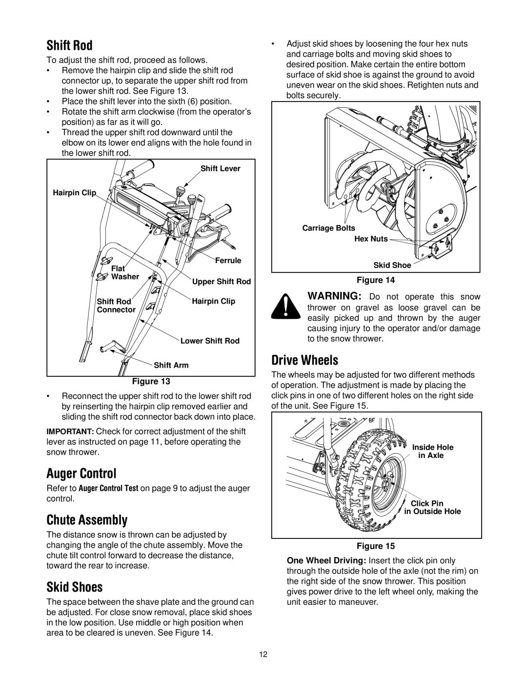
•Remove the hairpin clip and slide the shift rod connector up, to separate the upper shift rod from the lower shift rod. See Figure 13.
•Place the shift lever into the sixth (6) position.
•Rotate the shift arm clockwise (from the operator’s position) as far as it will go.
•Thread the upper shift rod downward until the elbow on its lower end aligns with the hole found in the lower shift rod.
| Shift Lever |
Hairpin Clip |
|
Flat | Ferrule |
| |
Washer | Upper Shift Rod |
| |
Shift Rod | Hairpin Clip |
Connector |
|
| Lower Shift Rod |
| Shift Arm |
Figure 13
•Reconnect the upper shift rod to the lower shift rod by reinserting the hairpin clip removed earlier and sliding the shift rod connector back down into place.
IMPORTANT: Check for correct adjustment of the shift lever as instructed on page 11, before operating the snow thrower.
Auger Control
Refer to Auger Control Test on page 9 to adjust the auger control.
Chute Assembly
The distance snow is thrown can be adjusted by changing the angle of the chute assembly. Move the chute tilt control forward to decrease the distance, toward the rear to increase.
Skid Shoes
The space between the shave plate and the ground can be adjusted. For close snow removal, place skid shoes in the low position. Use middle or high position when area to be cleared is uneven. See Figure 14.
•Adjust skid shoes by loosening the four hex nuts and carriage bolts and moving skid shoes to desired position. Make certain the entire bottom surface of skid shoe is against the ground to avoid uneven wear on the skid shoes. Retighten nuts and bolts securely.
Carriage Bolts |
Hex Nuts |
Skid Shoe |
Figure 14
WARNING: Do not operate this snow thrower on gravel as loose gravel can be easily picked up and thrown by the auger causing injury to the operator and/or damage to the snow thrower.
Drive Wheels
The wheels may be adjusted for two different methods of operation. The adjustment is made by placing the click pins in one of two different holes on the right side of the unit. See Figure 15.
Inside Hole |
in Axle |
Click Pin |
in Outside Hole |
Figure 15
One Wheel Driving: Insert the click pin only through the outside hole of the axle (not the rim) on the right side of the snow thrower. This position gives power drive to the left wheel only, making the unit easier to maneuver.
12