Manuals
/
MTD
/
Lawn and Garden
/
Lawn Mower
MTD
OHD 190-180
warranty
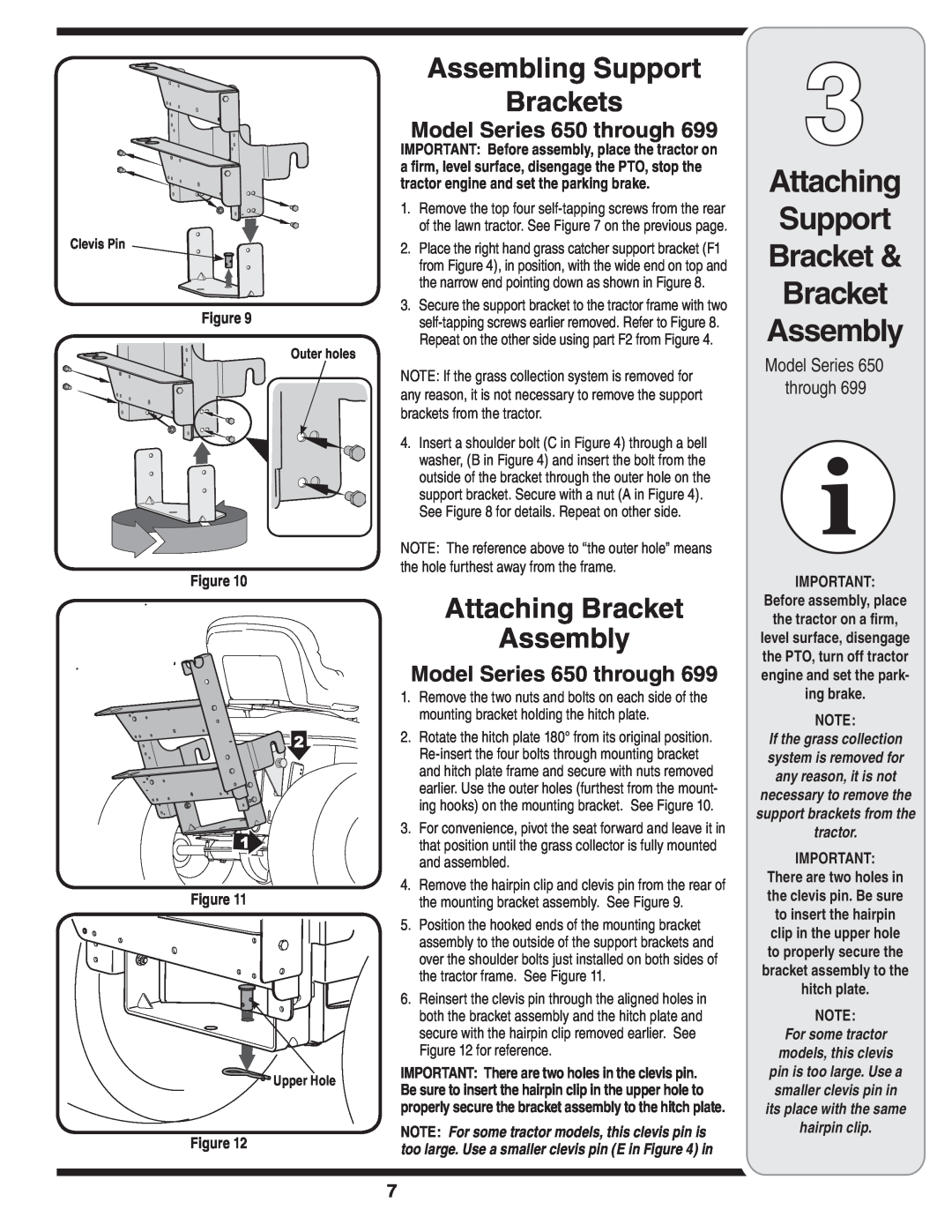
Attaching Support Bracket Bracket Assembly, Assembling Support Brackets
Models:
OHD 190-180
1
7
44
44
Download
44 pages
25.11 Kb
4
5
6
7
8
9
10
11
Attaching Bracket Assembly
Page 7
Image 7
Page 6
Page 8
Page 7
Image 7
Page 6
Page 8
Contents
Twin Rear Bagger Kit
READ SAFETY RULES AND INSTRUCTIONS CAREFULLY BEFORE OPERATION
OPERATOR’S MANUAL
To The Owner Carton Contents Assembly Parts Lists Warranty
BEFORE YOU START ASSEMBLING YOUR NEW EQUIPMENT
TABLE OF CONTENTS
Finding and Recording Model Number
Customer Support
Sample Model Number
FastAttach Twin Bag Grass Collector
Determine The Model of Your Rider
Rider Model Identification
One Chute Tube
Carton Contents
CONTENTS OF CARTON
toll free at
# = Quantity
CONTENTS OF HARDWARE PACK
RH = Right Hand LH = Left Hand
Before assembly, place the tractor on a firm
Attaching Bracket Assembly
Attaching The Bracket Assembly
Model Series 600 through
Model Series 650 through
Attaching Support Bracket Bracket Assembly
Attaching Bracket Assembly
Assembling Support Brackets
Inner Hole
Model Series
Self tap
screws
All Model Series
Attaching Grass Bags & Grass Bag Cover
Attaching Grass Bags Grass Bag Cover
600 through
On Older Model Riders
Attaching Discharge Chute
Discharge Chute
set the parking brake
Bagger Usage
All Model Series
All Models - 600 through
Rear Twin Bagger
For parts and/or accessories please call
Part List
Discharge Chute 38”/42” Bag
Grass catcher Cover Assembly
PART NUMBER
Hex Flange Lock Nut, 1/4-20
MANUFACTURER’S LIMITED WARRANTY FOR
IMPORTANTE
Kit de embolsado posterior doble
Modelos OHD-190-180
MANUAL DEL OPERADOR
ANTES DE COMENZAR A MONTAR SU NUEVO EQUIPO
Búsqueda y registro del número de modelo
Asistencia al cliente
ÍNDICE
FastAttach con sistema de bolsa doble
Identifi
cación del modelo de podadora tractor
Determine el modelo de la podadora tractor
CONTENIDO DE LA CAJA
Contenido de la caja
Un tubo de canal Un conjunto de canal de descarga
CONTENIDO DEL PAQUETE DE ELEMENTOS DE FERRETERÍA
Modelos series 650 a 699 inclusive
Instalación Conjunto de soporte
Instalación Conjunto de soporte
Modelos series 600 a inclusive
Ensamblado de los soportes
y del conjunto del soporte
Instalación del soporte
Instalación del conjunto del soporte
Vea la Figura
Instalación del soporte y del con- junto del so- porte
Ensamblado de los soportes
Modelo Serie
de pasto gire sobre el tubo de soporte y se abra Figura
series 600 a inclusive
Todos los modelos
Figura Figura Figura
Figura AB Figura Canal de descarga Figura
Instalación del canal de descarga
En tractores de modelos más antiguos
Todos los modelos series 600 a 699 inclusive NOTA
Tira de retención Pasador de la tolva para recorte de césped Figura
Uso de la embolsadora
Todas las series de modelos
Todos los modelos - 600 a inclusive
Lista de piezas
Embolsa dora doble posterior
Para piezas y/o accesorios por favor llame al
NÚMERO DE
Para piezas y/o
accesorios por favor llame al 1-800-800- 7310-6483 ó al
No. DE
g. Gastos de transporte y llamadas por servicios técnicos
GARANTÍA LIMITADA DEL FABRICANTE PARA
Esta garantía limitada no lo cubrirá en los siguientes casos
f. Piezas de reemplazo que no son piezas genuinas de MTD
IMPRIMÉ AUX
Collecteur arrière à deux sacs
Modèles OHD-190-180
MANUEL DE L’OPÉRATEUR
AVANT D’ASSEMBLER VOTRE NOUVEL ÉQUIPEMENT
Pour trouver et enregistrer le numéro de modèle
Support client
TABLE DES MATIERES
Déterminer le modèle de votre tracteur
Identification
du modèle du tracteur
Collecteur d’herbe à deux sacs FastAttach
CONTENU DU CARTON
Contenu du carton
PIÈCES DE QUINCAILLERIE
Modèles de série 650 à
Montage du support de fixation
Montage du support de fixation
Modèles de série 600 à
Modèle de série 650 à
Montage du
palier sup- port et du support de fixation
Montage des paliers supports
Modèle de la série
Modèle de la série
Voir la Figure
sacs à herbe et
Montage des sacs à herbe et du couvercle
Montage des
du couvercle
Sur les anciens modèles de tracteurs
Montage de
la goulotte d’éjection
Montage de la goulotte d’éjection
Patte de fixation Goupille du collecteur d’herbe
Utilisation du collecteur
Tous les modèles
Tous les modèles - Série 600 à
à deux sacs
Collecteur
Liste des pièces
Palier support Collecteur
NUMÉRO DE
DESCRIPTION
PIÈCE
Utilisez cette page pour noter les informa tions importantes
tions importantes
Utilisez cette page
pour noter les informa
f. Les pièces de rechange qui ne sont pas fabriquées par MTD
GARANTIE LIMITÉE DU FABRICANT
g. Les frais de transport et les appels de maintenance
Cette garantie limitée ne s’applique pas dans les cas suivants
Top
Page
Image
Contents