Series 580 specifications
The MTD Series 580 is a versatile and powerful machine that has garnered attention in the realm of outdoor equipment, known for its innovative features and robust performance. Designed primarily for homeowners and professional landscapers alike, this model stands out due to its combination of efficiency, durability, and user-friendly interface.One of the main features of the MTD Series 580 is its powerful engine, which typically ranges in displacement and power output, catering to various yard sizes and terrains. This powerful engine ensures that the machine can tackle tough tasks, including mowing extensive lawns, managing overgrown grass, and executing clean cuts in challenging environments.
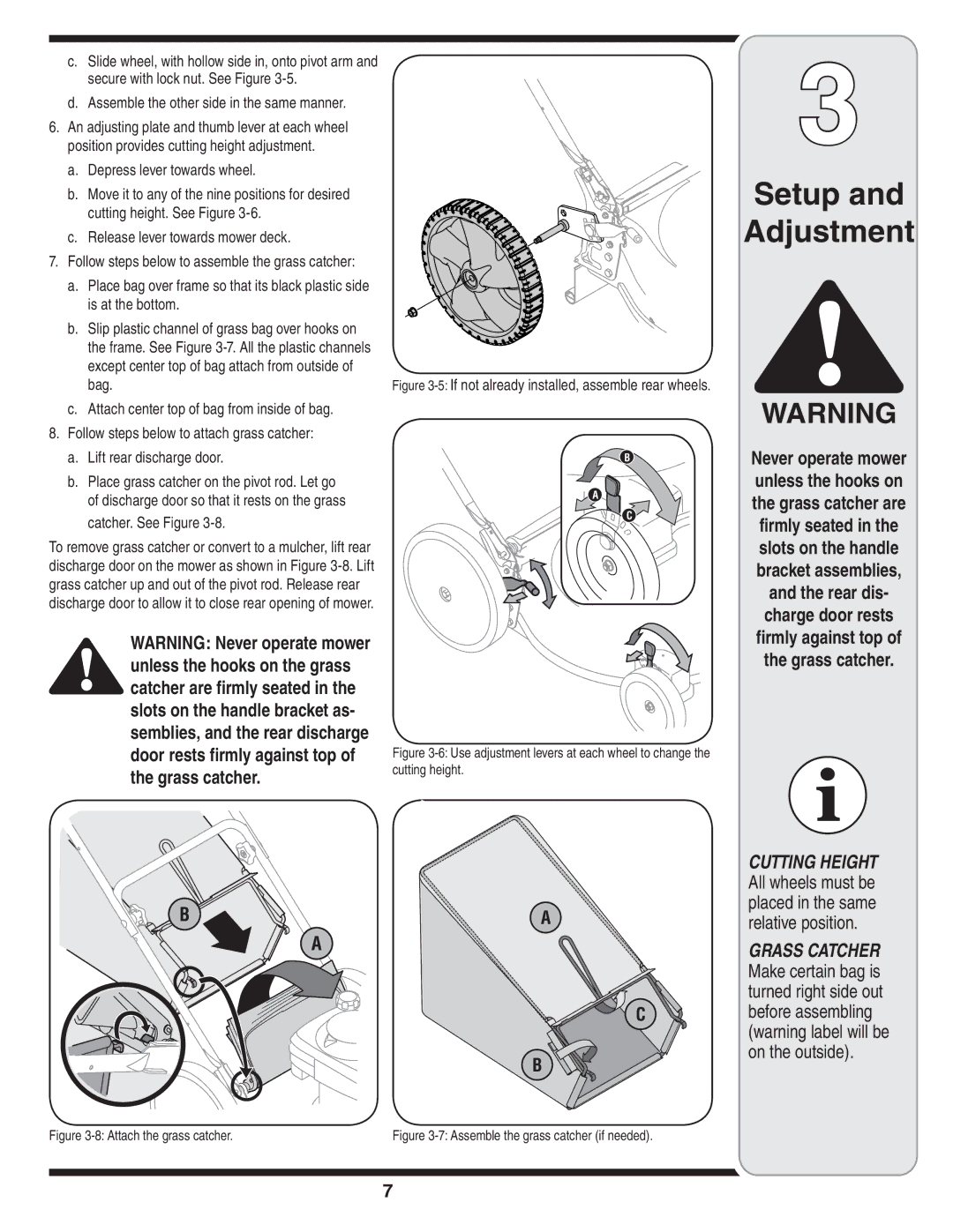
The MTD Series 580 incorporates advanced cutting technology, which includes a high-performance, mulching blade designed to deliver precision cuts while reducing grass clippings. This feature promotes a healthier lawn by allowing the mulched grass clippings to decompose naturally, returning essential nutrients back to the soil. Additionally, the adjustable cutting height feature allows users to customize their mowing preferences, ensuring that they can achieve the exact grass length desired.
Ergonomics and comfort are central to the design of the MTD Series 580. With an adjustable seat and an intuitive control panel, operators can easily maneuver the machine for prolonged periods without discomfort. The easy-to-reach controls simplify operation, making it suitable for both professionals and DIY enthusiasts.
Moreover, the MTD Series 580 comes equipped with advanced safety features, including automatic blade brakes and enhanced stability controls. This ensures that users can operate the machine safely, even on uneven terrain. The robust construction of the chassis not only provides stability but also enhances the overall longevity of the machine, with high-quality materials designed to withstand harsh outdoor conditions.
Another notable characteristic of the MTD Series 580 is its fuel efficiency, made possible by the innovative engine technology that minimizes emissions and maximizes power output. This makes the machine environmentally friendly while saving on operational costs, a growing concern among today’s eco-conscious consumers.
In summary, the MTD Series 580 is more than just an outdoor machine; it represents a blend of power, safety, and comfort, tailored to meet the demands of both homeowners and professionals. With its advanced features and technologies, it stands out as a reliable investment for tackling various outdoor challenges effectively and efficiently.

