AMPLIFIERS
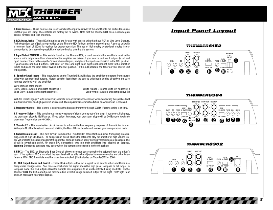
1.Gain Controls – These controls are used to match the input sensitivity of the amplifier to the particular source unit that you are using. The controls are factory set to 1Vrms. Note that the Thunder6304 has a separate gain control for front and rear channels.
2.RCA Input Jacks – These RCA input jacks are for use with source units that have RCA or Line Level Outputs. An independent set of jacks are provided on the Thunder6304 for front and rear stereo inputs. A source unit with a minimum level of 200mV is required for proper operation. The use of high quality twisted pair cables is rec- ommended to decrease the possibility of radiated noise entering the system.
3.Input Select 2CH/4CH – This switch, found on the Thunder6304, is used to match the amplifier’s input to the source unit’s output so all four channels of the amplifier are driven. If your source unit has 2 outputs (a left and right) connect them to the amplifier’s front channel inputs, and place the input select switch in the 2CH position. If your source unit has 4 outputs, (left front, left rear, and right front, right rear) connect them to the amplifier inputs and place the input select switch in the 4CH postion. In the 4CH position, the fader on your source unit will operate.
4.Speaker Level Inputs – This input, found on the Thunder6152 will allow the amplifier to operate from source units with
Wire harness color codes: |
|
Grey / Black = Source units right negative | White / Black = Source units left negative |
Solid Grey = Source units right positive (+) | Solid White = Source units left positive (+) |
With the
5.Frequency Control – This control is continuously adjustable from 40Hz through 200Hz. Factory setting is at 40Hz.
6.Crossover Select – This switch determines what type of signal comes out of the amp. If you select high pass, the crossover slope is 12dB/stereo. If you select low pass, your crossover slope will be 24dB/mono. Available crossover frequencies are
7.Thunder EQ – This equalization circuit is used to enhance the low frequency response of the vehicle’s interior. With up to 18 dB of boost and centered at 40Hz, the Bass EQ can be adjusted to meet your own personal taste.
8.Compression Circuit – This new circuit, found on the Thunder8302, prevents the amplifier from going into clip- ping, even at high SPL levels. The compression circuit allows the listener to play the amplifier at high volume lev- els, yet protects the speakers against the potential damage that can occur during dynamic musical passages. The circuit is switchable on/off, for those SPL competitors who run their amplifiers into clipping on purpose. Warning: Damage to speakers may occur when the compression circuit is in the off position.
9.EBC 2 – The EBC, or Electronic Bass Control, allows a remote bass control to be adjusted from the driver’s seat. If the optional EBC is installed, the bass level will be able to be adjusted to overcome noise and other inter- ference. With EBC 2 multiple amplifiers can be controlled. (Not included on Thunder6152 or 6304)
10.RCA Output Jacks and Switch – These RCA outputs allow for a signal to be sent to other amplifiers in a
![]() 4
4
Input Panel Layout | |||
|
|
| ❹ |
❶ ❼ ❷ ❿ | ❻ ❺ ❿ |
| |
❶❼❺ ❻ | ❷ | ❿ ❷ ❻ ❺❼❶ | |
| ❸ |
|
|
|
|
| ❽ |
❶ ❼ ❷ ❿ | ❻ ❺ ❿ | ➒ | |
|
|
| 5 |