Chapter 2 - Installation & Connection
Controls on PC Board
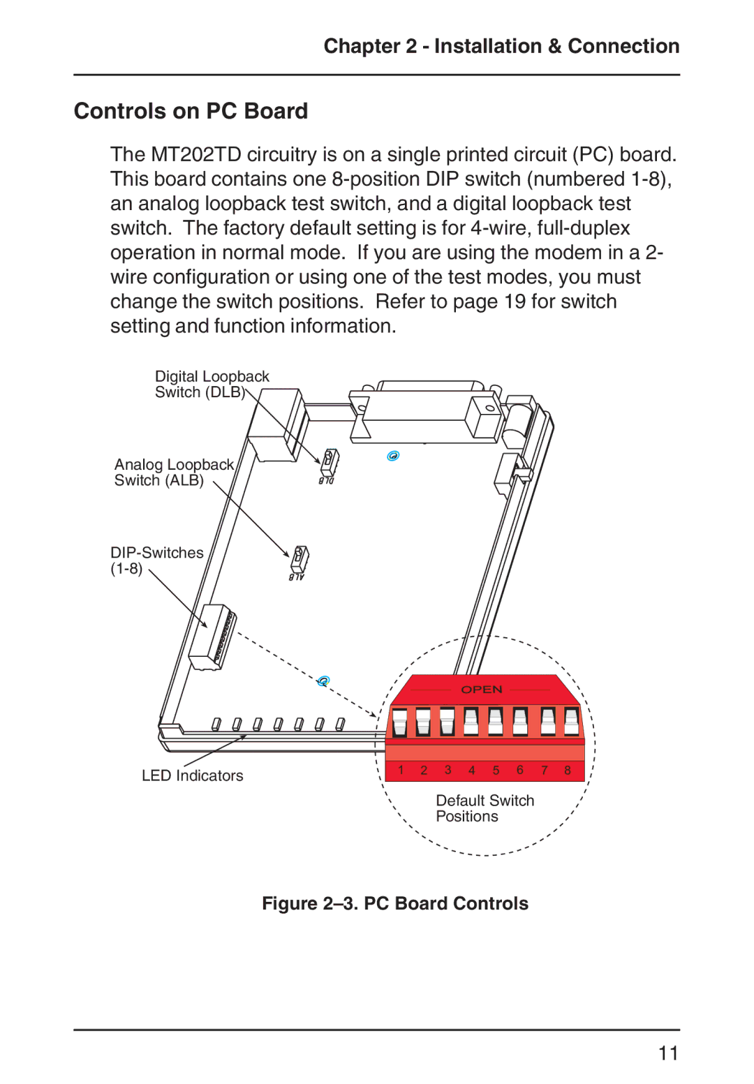
The MT202TD circuitry is on a single printed circuit (PC) board. This board contains one 8-position DIP switch (numbered 1-8), an analog loopback test switch, and a digital loopback test switch. The factory default setting is for 4-wire, full-duplex operation in normal mode. If you are using the modem in a 2- wire configuration or using one of the test modes, you must change the switch positions. Refer to page 19 for switch setting and function information.
Digital Loopback
Switch (DLB)
Analog Loopback
Switch (ALB)
DIP-Switches (1-8)
1 2 3 4 5 6 7 8
Default Switch
Positions
Figure 2–3. PC Board Controls