This ChannelPlus 3400 Series video distribution system contains
Models available:
3425 2 channel system
3445 4 channel system
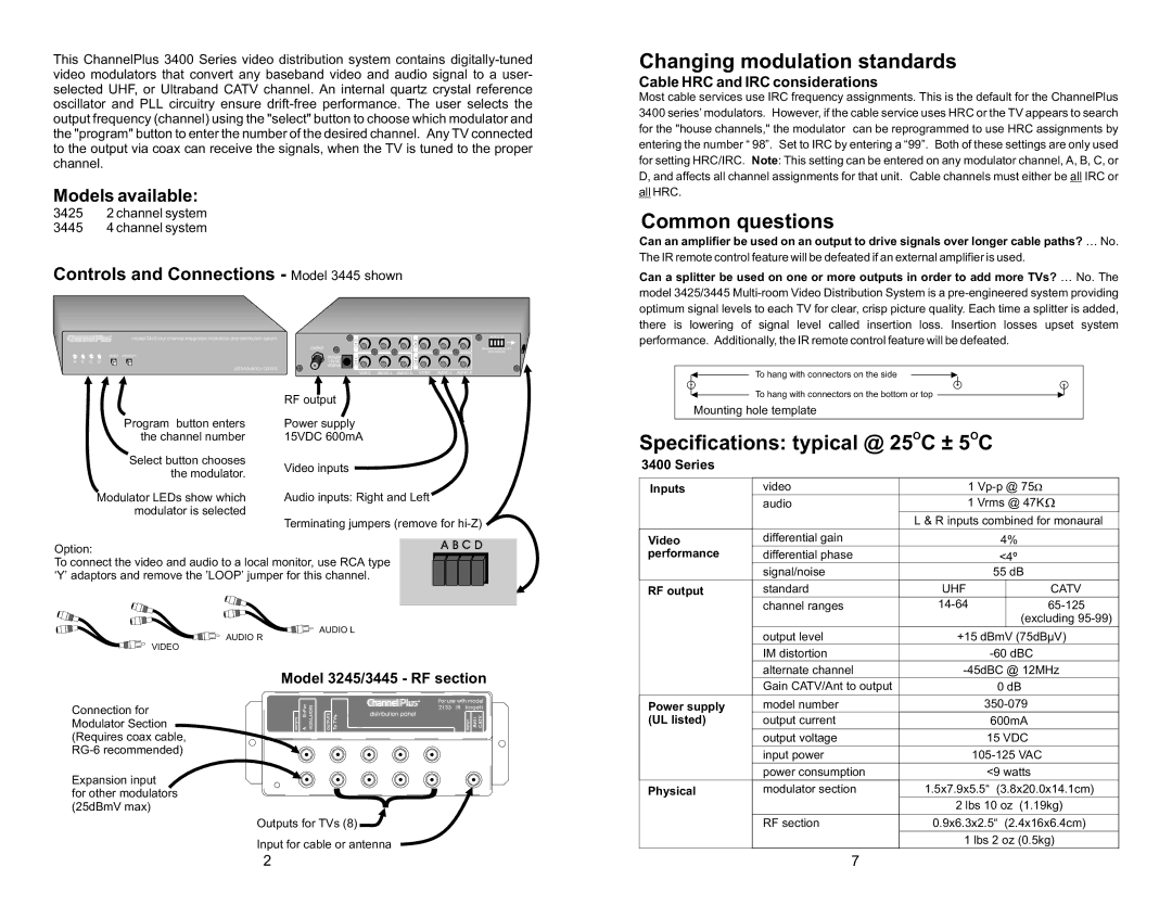
Controls and Connections - Model 3445 shown
|
|
| ® |
|
|
|
|
|
|
| A B C D |
|
|
|
| model 3445 four channel integrated modulator and distribution system |
| D |
|
| B |
| |
|
|
|
|
|
|
|
|
| |||
|
|
|
|
| OUTPUT | CH |
|
| CH |
| Remove jumper for |
|
|
|
|
|
|
|
|
|
| ||
|
|
|
|
|
|
|
|
|
|
| (See manual) |
|
|
| select | program | POWER | C |
|
| A |
|
|
|
|
|
|
|
|
|
|
| |||
A | B | C | D |
| 15VDC | CH |
|
| CH |
|
|
|
|
|
| pll frequency control | 600mA |
|
|
|
| ||
|
|
|
|
|
|
|
|
|
|
| |
|
|
|
|
|
| VIDEO | AUDIO L | AUDIO R | VIDEO | AUDIO L | AUDIO R |
Changing modulation standards
Cable HRC and IRC considerations
Most cable services use IRC frequency assignments. This is the default for the ChannelPlus 3400 series’ modulators. However, if the cable service uses HRC or the TV appears to search for the "house channels," the modulator can be reprogrammed to use HRC assignments by entering the number “ 98”. Set to IRC by entering a “99”. Both of these settings are only used for setting HRC/IRC. Note: This setting can be entered on any modulator channel, A, B, C, or D, and affects all channel assignments for that unit. Cable channels must either be all IRC or all HRC.
Common questions
Can an amplifier be used on an output to drive signals over longer cable paths? … No.
The IR remote control feature will be defeated if an external amplifier is used.
Can a splitter be used on one or more outputs in order to add more TVs? … No. The model 3425/3445
To hang with connectors on the side
Program button enters the channel number
Select button chooses the modulator.
Modulator LEDs show which modulator is selected
RF output
Power supply 15VDC 600mA
Video inputs
Audio inputs: Right and Left
Terminating jumpers (remove for
To hang with connectors on the bottom or top ![]()
Mounting hole template
Specifications: typical @ 25OC ± 5OC
3400 Series
Inputs | video | 1 |
| audio | 1 Vrms @ 47K |
|
| L & R inputs combined for monaural |
|
|
|
Video | differential gain | 4% |
Option: |
|
| A B C D | |
|
|
|
| |
To connect the video and audio to a local monitor, use RCA type |
| |||
‘Y’ adaptors and remove the ’LOOP’ jumper for this channel. |
| |||
| AUDIO R | AUDIO L |
|
|
|
|
|
| |
VIDEO |
|
|
|
|
| Model 3245/3445 - RF section | |||
Modulator Section | INPUTS AB+Pwr MODULATORS | OUTPUTS ToTVs | For use with model | |
2133 | INPUT Ant/ CATV | |||
Connection for |
|
| distribution panel |
|
(Requires coax cable, |
|
|
|
|
|
|
|
| |
Expansion input |
|
| } |
|
for other modulators |
|
|
| |
(25dBmV max) |
|
|
| |
Outputs for TVs (8) ![]()
Input for cable or antenna
performance | differential phase |
| <4º | |
| signal/noise |
| 55 dB | |
|
|
|
|
|
RF output | standard | UHF |
| CATV |
| channel ranges |
| ||
|
|
|
| (excluding |
|
|
|
| |
| output level | +15 dBmV (75dBµV) | ||
| IM distortion |
| ||
| alternate channel | |||
| Gain CATV/Ant to output |
| 0 dB | |
Power supply | model number | |||
(UL listed) | output current |
| 600mA | |
|
|
|
| |
| output voltage | 15 VDC | ||
|
|
|
| |
| input power | |||
|
|
|
| |
| power consumption | <9 watts | ||
Physical | modulator section | 1.5x7.9x5.5“ | (3.8x20.0x14.1cm) | |
|
| 2 lbs 10 oz (1.19kg) | ||
|
|
|
| |
| RF section | 0.9x6.3x2.5“ (2.4x16x6.4cm) | ||
|
| 1 lbs 2 oz (0.5kg) | ||
|
|
|
|
|
2 | 7 |