Things to watch for:
No picture … Verify that the video source is on and is producing a video signal. Check that the TV and the modulator are tuned to the same channel. For example, if the modulator is broadcasting on UHF channel 16, make sure the TV is on UHF 16 rather than CATV 16. UHF 16 and CATV 16 are at different frequencies.
Weak ChannelPlus UHF channel … If the TV has a separate UHF input, be sure that it is connected.
LEDs blink ... You need to have one unused channel space between channels. The display will blink if you have made an ‘illegal’ choice. See the section on programming.
Herringbone interference on ChannelPlus channel (diagonal lines) ...
You may have chosen a channel number that is not completely vacant. Distant UHF stations may be
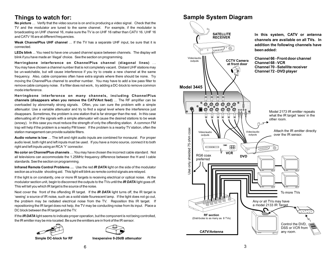
Sample System Diagram
| SATELLITE | In this system, CATV or antenna | |
| RECEIVER | channels are available on all TVs. In | |
|
| ||
|
| addition the following channels have | |
|
| been added: | |
Video/audio | CCTV Camera | Channel 66 | - Front door channel |
outputs | Channel 68 | - VCR | |
| at front door | ||
| Channel 70 | - Satellite receiver | |
|
| ||
|
| Channel 72 | - DVD player |
mode interference.
Herringbone interference on many channels, including ChannelPlus
channels (disappears when you remove the CATV/Ant feed) … The RF amplifier can be overloaded by abnormally strong signals. Often, you can cure the problem with a simple attenuator. Use a variable attenuator and try to find a signal level where the interference just disappears. Sometimes, the problem is one station that is far stronger than the rest. In this case attenuating all of the signals with a simple attenuator will cause the desired stations to be weak (snowy). In this case you must reduce the strength of only the offending station. A common FM trap will help if the problem is a nearby FM tower. If the problem is a nearby TV station, often the
Model 3445
| CH D |
|
| CH B |
| A B C D |
OUTPUT |
|
|
|
| ||
|
|
|
|
| Remove jumper for | |
| C |
|
|
|
| (See manual) |
POWER |
|
| A |
|
| |
15VDC | CH |
|
| CH |
|
|
600mA |
|
|
|
|
|
|
| VIDEO | AUDIO L | AUDIO R | VIDEO | AUDIO L | AUDIO R |
Model 2173 IR emitter repeats what the IR target ‘sees’ in the other room.
station management can provide suitable filters.
Audio volume is low … The left and right audio inputs are combined for monaural. For proper audio level, both right and left inputs must be used. If you have a mono source, connect it to both right and left inputs using an RCA ‘Y’ connector.
No color on ChannelPlus channels … You may have chosen the incorrect cable standard. Not all televisions can accommodate the 1.25MHz frequency difference between the H and I cable standards. See the section on programming.
Infrared Remote Control Problems … Use the red IR DATA light on the side of the modulator section as a trouble shooting aid. This light will blink as remote control signals are relayed.
If the light is on constantly, one or more IR targets is receiving electrical or optical noise. At the modulator section unit, begin to disconnect the outputs to the TVs until the IR DATA light goes off. This will tell you which IR target is the source of the noise.
Next cover the front of the offending IR target. If the IR DATA light turns off, the IR target is
Use only shielded 75 ohm coax
Video/audio | Video/audio | |
outputs | outputs | |
| 12:00 | |
VCR |
| |
RG6 coax | VCR | |
DVD | ||
preferred | ||
|
Attach the IR emitter directly over the IR sensor.
To more TVs
‘seeing’ a source of IR noise, such as a solid state flourescent lamp. If the light does not go out, the problem may be radiated electrical noise from the TV. Reposition this IR target. If repositioning the IR target does not help, the TV may be conducting noise from its input. Place a DC block between the IR target and the TV.
If the IR DATA light seems to indicate proper operation, but the component is not being controlled, the IR emitter may be
Simple | Inexpensive |
| Any or all TVs may have |
| a model 2133 IR Target |
RF section |
|
(Distributes to as many as 8 TVs) |
|
| Control the DVD, |
| DSS or VCR from |
CATV/Antenna | any room. |
6 | 3 |