GENERATOR OUTPUTS
Generator Output Voltages
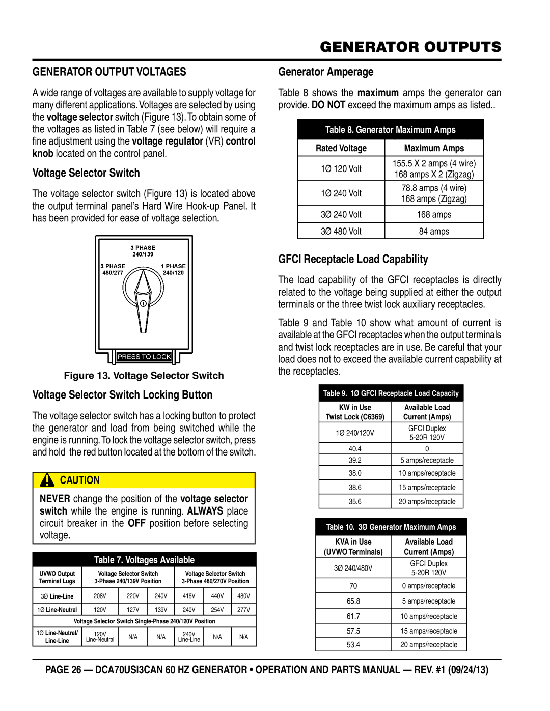
A wide range of voltages are available to supply voltage for many different applications.Voltages are selected by using the voltage selector switch (Figure 13). To obtain some of the voltages as listed in Table 7 (see below) will require a fine adjustment using the voltage regulator (VR) control knob located on the control panel.
Voltage Selector Switch
The voltage selector switch (Figure 13) is located above the output terminal panel’s Hard Wire
Generator Amperage
Table 8 shows the maximum amps the generator can provide. DO NOT exceed the maximum amps as listed..
Table 8. Generator Maximum Amps
Rated Voltage | Maximum Amps | |
|
| |
1Ø 120 Volt | 155.5 X 2 amps (4 wire) | |
168 amps X 2 (Zigzag) | ||
| ||
1Ø 240 Volt | 78.8 amps (4 wire) | |
168 amps (Zigzag) | ||
| ||
3Ø 240 Volt | 168 amps | |
|
| |
3Ø 480 Volt | 84 amps | |
|
|
Figure 13. Voltage Selector Switch
Voltage Selector Switch Locking Button
The voltage selector switch has a locking button to protect the generator and load from being switched while the engine is running.To lock the voltage selector switch, press and hold the red button located at the bottom of the switch.
CAUTION
NEVER change the position of the voltage selector switch while the engine is running. ALWAYS place circuit breaker in the OFF position before selecting voltage.
Table 7. Voltages Available
UVWO Output | Voltage Selector Switch | Voltage Selector Switch | |||||
Terminal Lugs | |||||||
|
|
|
|
|
|
| |
3Ø | 208V | 220V | 240V | 416V | 440V | 480V | |
|
|
|
|
|
|
| |
1Ø | 120V | 127V | 139V | 240V | 254V | 277V | |
|
|
|
|
|
|
| |
Voltage Selector Switch |
| ||||||
|
|
|
|
|
|
| |
1Ø | 120V | N/A | N/A | 240V | N/A | N/A | |
|
|
|
| ||||
|
|
|
|
|
|
| |
GFCI Receptacle Load Capability
The load capability of the GFCI receptacles is directly related to the voltage being supplied at either the output terminals or the three twist lock auxiliary receptacles.
Table 9 and Table 10 show what amount of current is available at the GFCI receptacles when the output terminals and twist lock receptacles are in use. Be careful that your load does not to exceed the available current capability at the receptacles.
Table 9. 1Ø GFCI Receptacle Load Capacity
KW in Use | Available Load | |
Twist Lock (C6369) | Current (Amps) | |
1Ø 240/120V | GFCI Duplex | |
| ||
40.4 | 0 | |
39.2 | 5 amps/receptacle | |
38.0 | 10 amps/receptacle | |
|
| |
38.6 | 15 amps/receptacle | |
|
| |
35.6 | 20 amps/receptacle | |
|
|
Table 10. 3Ø Generator Maximum Amps
KVA in Use | Available Load | |
(UVWO Terminals) | Current (Amps) | |
3Ø 240/480V | GFCI Duplex | |
| ||
70 | 0 amps/receptacle | |
|
| |
65.8 | 5 amps/receptacle | |
|
| |
61.7 | 10 amps/receptacle | |
|
| |
57.5 | 15 amps/receptacle | |
|
| |
53.4 | 20 amps/receptacle | |
|
|
page 26 — DCA70USI3can 60 hz Generator • operation and parts manual — rev. #1 (09/24/13)