FS2 CONCRETE SAW — MAINTENANCE
Raise/Lower Height Adjustment
The FS2 is equipped with an Raise/ Lower assembly that is supported by the following:
λACME Screw
λPrecision Thread
λDepth Gauge Bearing
λDepth Gauge Pointer
λTube Height Adjustment
The height adjustment of the FS2 has been factory set utilizing precision standards.
Reference Manual Raise and Lower Assembly on page 52 unless otherwise noted.
Setting The Height Of The Depth Gauge Pointer
Perform the following to set the height of the Depth Gauge Pointer:
1.Place the saw on a level working surface.
2.Remove the rear panel cover, see page 46, item 9.
3.Install an appropriate new diamond blade on the saw and take reference to the diameter.
4.Lower the blade until flush contact is made with the level surface.
5.Loosen the two hex nuts, item 18, that tighten against the upper and lower rod ends, item 19.
6.Loosen the hex nut, item 13, that secures the plunge ball, item 12, depth lock against the adjustment tube.
7.Loosen
8.Set the blade height indicator to "0" (relative to the diameter of the blade and depth scale). See Figure 6, "Concrete Saw Console".
10.Remove the upper
11.Adjust the rod ends as required to ensure that the throw of both rod ends and threaded rod, item 14, support the "0" position of the depth gauge located on the console.
12.Tighten the plunge ball, item 12, to the full depth against the ACME screw, item 9.
13.Unscrew the plunge ball, item 12, 1 FULL TURN (counter- clockwise).
14.Tighten the hex nuts, item 13, against the "Adjustment Tube", item 10, to lock the plunge ball in place.
V-Belt Tension Check
Check tension after first day of operations, then weekly/or 25 hours. Replace as required (see Figure 14). NEVER operate
with less than 3 belts.
The FS2 is equipped with (3) premium 3VX
The saw must be operated with all (3)
The
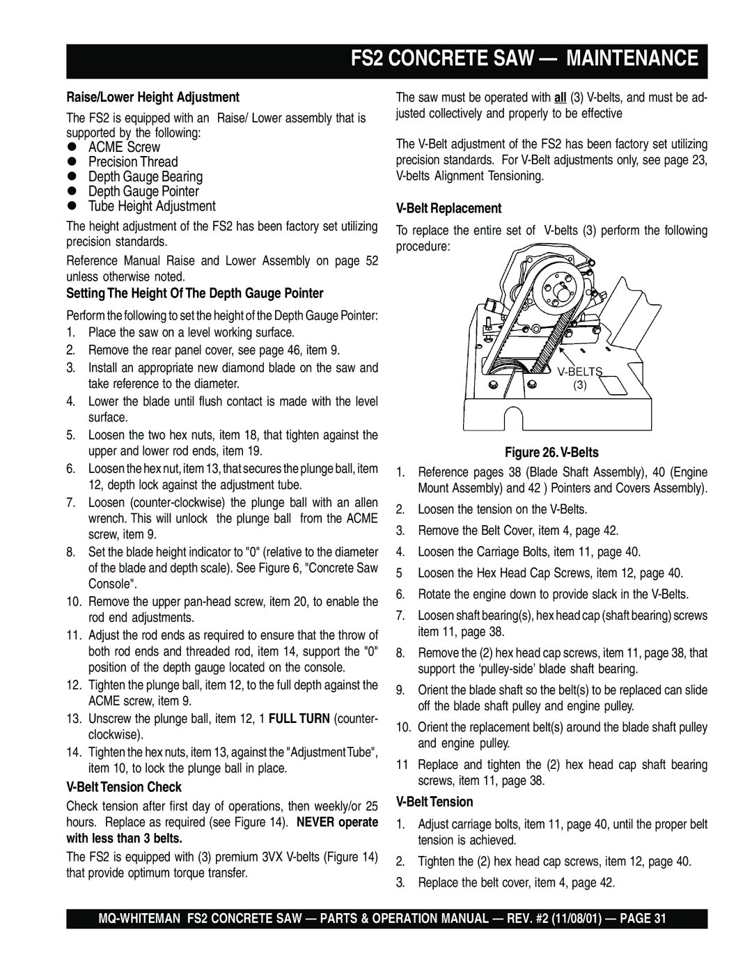
V-Belt Replacement
To replace the entire set of
Figure 26. V-Belts
1.Reference pages 38 (Blade Shaft Assembly), 40 (Engine Mount Assembly) and 42 ) Pointers and Covers Assembly).
2.Loosen the tension on the
3.Remove the Belt Cover, item 4, page 42.
4.Loosen the Carriage Bolts, item 11, page 40.
5 Loosen the Hex Head Cap Screws, item 12, page 40.
6.Rotate the engine down to provide slack in the
7.Loosen shaft bearing(s), hex head cap (shaft bearing) screws item 11, page 38.
8.Remove the (2) hex head cap screws, item 11, page 38, that support the
9.Orient the blade shaft so the belt(s) to be replaced can slide off the blade shaft pulley and engine pulley.
10.Orient the replacement belt(s) around the blade shaft pulley and engine pulley.
11Replace and tighten the (2) hex head cap shaft bearing screws, item 11, page 38.
V-Belt Tension
1.Adjust carriage bolts, item 11, page 40, until the proper belt tension is achieved.
2.Tighten the (2) hex head cap screws, item 12, page 40.
3.Replace the belt cover, item 4, page 42.