MQ GA-2.9R— INITIAL START-UP ENGINE/OPERATION
6.If the engine has started, slowly return the choke lever (Figure 12 ) to the “OPEN” position. If the engine has not started repeat steps 1 through 5.
7.Beforethegeneratorisplacedintooperation,runtheengine for
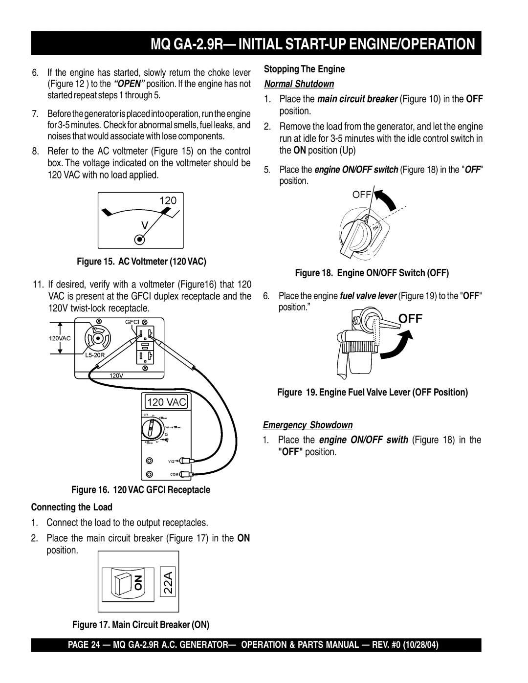
8.Refer to the AC voltmeter (Figure 15) on the control box. The voltage indicated on the voltmeter should be 120 VAC with no load applied.
Figure 15. AC Voltmeter (120 VAC)
11.If desired, verify with a voltmeter (Figure16) that 120 VAC is present at the GFCI duplex receptacle and the 120V
Figure 16. 120 VAC GFCI Receptacle
Connecting the Load
1.Connect the load to the output receptacles.
2.Place the main circuit breaker (Figure 17) in the ON position.
Stopping The Engine
Normal Shutdown
1.Place the main circuit breaker (Figure 10) in the OFF position.
2.Remove the load from the generator, and let the engine run at idle for
5.Place the engine ON/OFF switch (Figure 18) in the "OFF" position.
Figure 18. Engine ON/OFF Switch (OFF)
6.Place the engine fuel valve lever (Figure 19) to the "OFF" position.”
Figure 19. Engine Fuel Valve Lever (OFF Position)
Emergency Showdown
1.Place the engine ON/OFF swith (Figure 18) in the "OFF" position.
Figure 17. Main Circuit Breaker (ON)
PAGE 24 — MQ