J-SERIESTROWEL — MAINTENANCE
2.Start engine, and bring trowel blades up to full speed and look for the following conditions:
■Does the trowel have a perceived rolling or bouncing motion when in use?
■Look at the trowel while it is running, does the guard ring “rock up and down” relative to the ground?
Spider Removal
1.Onceitisdeterminedthatanadjustmentisrequired,remove the spider assembly from the gearbox shaft as follows:
a.Locate the cone point square head set screw (Figure 41) and attached jam nut found on the side of the spider assembly.
b.Loosen the jam nut and cone point square head set screw,andcarefullyliftthe uppertrowelassemblyoff ofthespiderassembly. Aslighttapwitharubbermallet maybenecessarytodislodgethespiderfromthemain shaft of the gearbox.
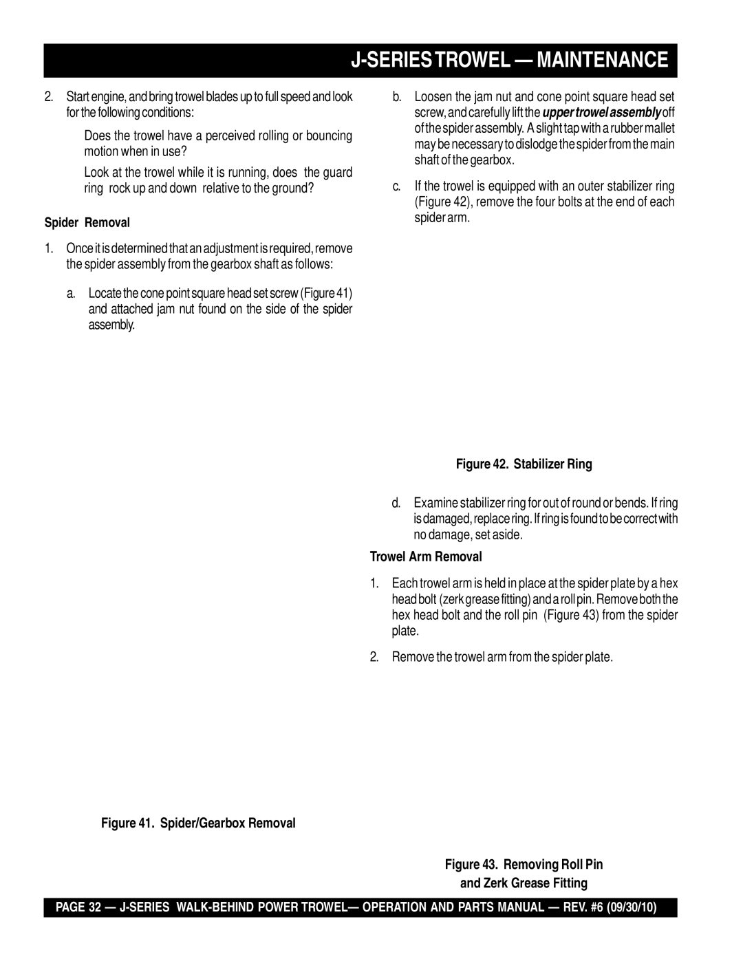
c.If the trowel is equipped with an outer stabilizer ring (Figure 42), remove the four bolts at the end of each spider arm.
Figure 42. Stabilizer Ring
d.Examine stabilizer ring for out of round or bends. If ring isdamaged,replacering.Ifringisfoundtobecorrectwith no damage, set aside.
Trowel Arm Removal
1.Each trowel arm is held in place at the spider plate by a hex headbolt (zerkgreasefitting)andarollpin.Removeboththe hex head bolt and the roll pin (Figure 43) from the spider plate.
2.Remove the trowel arm from the spider plate.
Figure 41. Spider/Gearbox Removal
Figure 43. Removing Roll Pin
and Zerk Grease Fitting
PAGE 32 —