operation

Connecting Dual float Switch (SW-1WOP) To Control Box

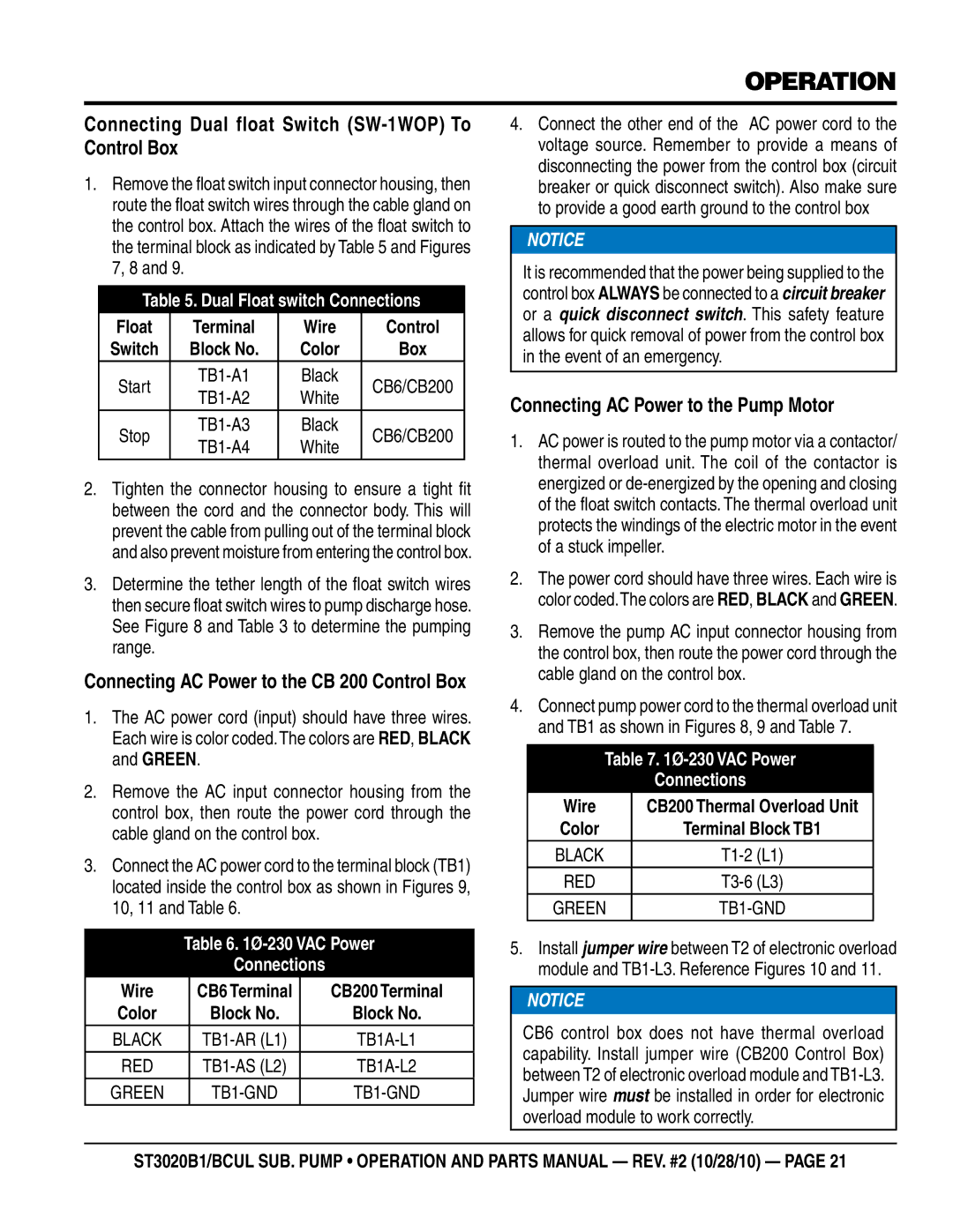
1.Remove the float switch input connector housing, then route the float switch wires through the cable gland on the control box. Attach the wires of the float switch to the terminal block as indicated by Table 5 and Figures 7, 8 and 9.

Table 5. Dual Float switch Connections

Float

Terminal

Wire

Control

Switch

Block No.

Color

Box

Start

TB1-A1

Black

CB6/CB200

TB1-A2

White


Stop

TB1-A3

Black

CB6/CB200

TB1-A4

White


2.Tighten the connector housing to ensure a tight fit between the cord and the connector body. This will prevent the cable from pulling out of the terminal block and also prevent moisture from entering the control box.

3.Determine the tether length of the float switch wires then secure float switch wires to pump discharge hose. See Figure 8 and Table 3 to determine the pumping range.

Connecting AC Power to the CB 200 Control Box

1.The AC power cord (input) should have three wires. Each wire is color coded.The colors are RED, BLACK and GREEN.

2.Remove the AC input connector housing from the control box, then route the power cord through the cable gland on the control box.

3.Connect the AC power cord to the terminal block (TB1) located inside the control box as shown in Figures 9, 10, 11 and Table 6.

Table 6. 1Ø-230 VAC Power

Connections

Wire

CB6 Terminal

CB200 Terminal

Color

Block No.

Block No.

BLACK

TB1-AR (L1)

TB1A-L1

RED

TB1-AS (L2)

TB1A-L2

GREEN

TB1-GND

TB1-GND

4.Connect the other end of the AC power cord to the voltage source. Remember to provide a means of disconnecting the power from the control box (circuit breaker or quick disconnect switch). Also make sure to provide a good earth ground to the control box

NOTICE

It is recommended that the power being supplied to the control box ALWAYS be connected to a circuit breaker or a quick disconnect switch. This safety feature allows for quick removal of power from the control box in the event of an emergency.

Connecting AC Power to the Pump Motor

1.AC power is routed to the pump motor via a contactor/ thermal overload unit. The coil of the contactor is energized or de-energized by the opening and closing of the float switch contacts. The thermal overload unit protects the windings of the electric motor in the event of a stuck impeller.

2.The power cord should have three wires. Each wire is color coded.The colors are RED, BLACK and GREEN.

3.Remove the pump AC input connector housing from the control box, then route the power cord through the cable gland on the control box.

4.Connect pump power cord to the thermal overload unit and TB1 as shown in Figures 8, 9 and Table 7.

Table 7. 1Ø-230 VAC Power

Connections

Wire

CB200 Thermal Overload Unit

Color

Terminal Block TB1

BLACK

T1-2 (L1)

RED

T3-6 (L3)

GREEN

TB1-GND

5.Install jumper wire between T2 of electronic overload module and TB1-L3. Reference Figures 10 and 11.

NOTICE

CB6 control box does not have thermal overload capability. Install jumper wire (CB200 Control Box) between T2 of electronic overload module and TB1-L3. Jumper wire must be installed in order for electronic overload module to work correctly.

st3020b1/BCUL Sub. pump • operation and parts manual — rev. #2 (10/28/10) — page 21

Page 21
Image 21
Multiquip st3020b1, st3020bcul Connecting Dual float Switch SW-1WOP To Control Box, Connecting AC Power to the Pump Motor

st3020bcul, st3020b1 specifications

The Multiquip ST3020B1 and ST3020BCUL are robust and efficient generators designed to meet the power needs of various applications. These models are particularly popular among contractors, events, and emergency services due to their reliability and high performance.

One of the main features of the ST3020B1 is its impressive power output. With a rated capacity of 30 kW, this generator is capable of powering a variety of tools and equipment simultaneously. The ST3020BCUL variant, while also maintaining similar power output, offers additional features that enhance usability and functionality. Both models are equipped with a durable frame and come with advanced noise-reduction technology, making them suitable for use in noise-sensitive environments.

The design of the ST3020B1 and ST3020BCUL emphasizes portability. Both models are fitted with heavy-duty wheels and ergonomic handles, allowing for easy maneuverability across job sites. Their compact design ensures that they occupy minimal space without compromising on performance.

In terms of technology, these generators are powered by a reliable engine that guarantees consistent performance. The advanced fuel consumption management system enhances efficiency, allowing longer operational periods before refueling. Additionally, the generators are designed with user-friendly control panels that provide clear indicators for oil levels, battery voltage, and running status, ensuring easy monitoring during operation.

Safety features are paramount in the design of the ST3020B1 and ST3020BCUL. Both models are equipped with Automatic Low Oil Shutdown systems, preventing engine damage and ensuring longevity. The overload protection mechanism safeguards against potential equipment damage by automatically shutting down the generator when necessary.

Moreover, the ST3020BCUL model goes a step further by integrating additional outputs, including multiple 120V and 240V outlets, catering to diverse power requirements. This versatility makes it ideal for both professional construction environments and recreational applications.

In summary, the Multiquip ST3020B1 and ST3020BCUL generators stand out for their powerful output, portability, user-friendly technology, and safety features. These characteristics make them an essential tool for anyone requiring reliable mobile energy solutions, contributing significantly to enhanced productivity and efficiency in various operational settings.