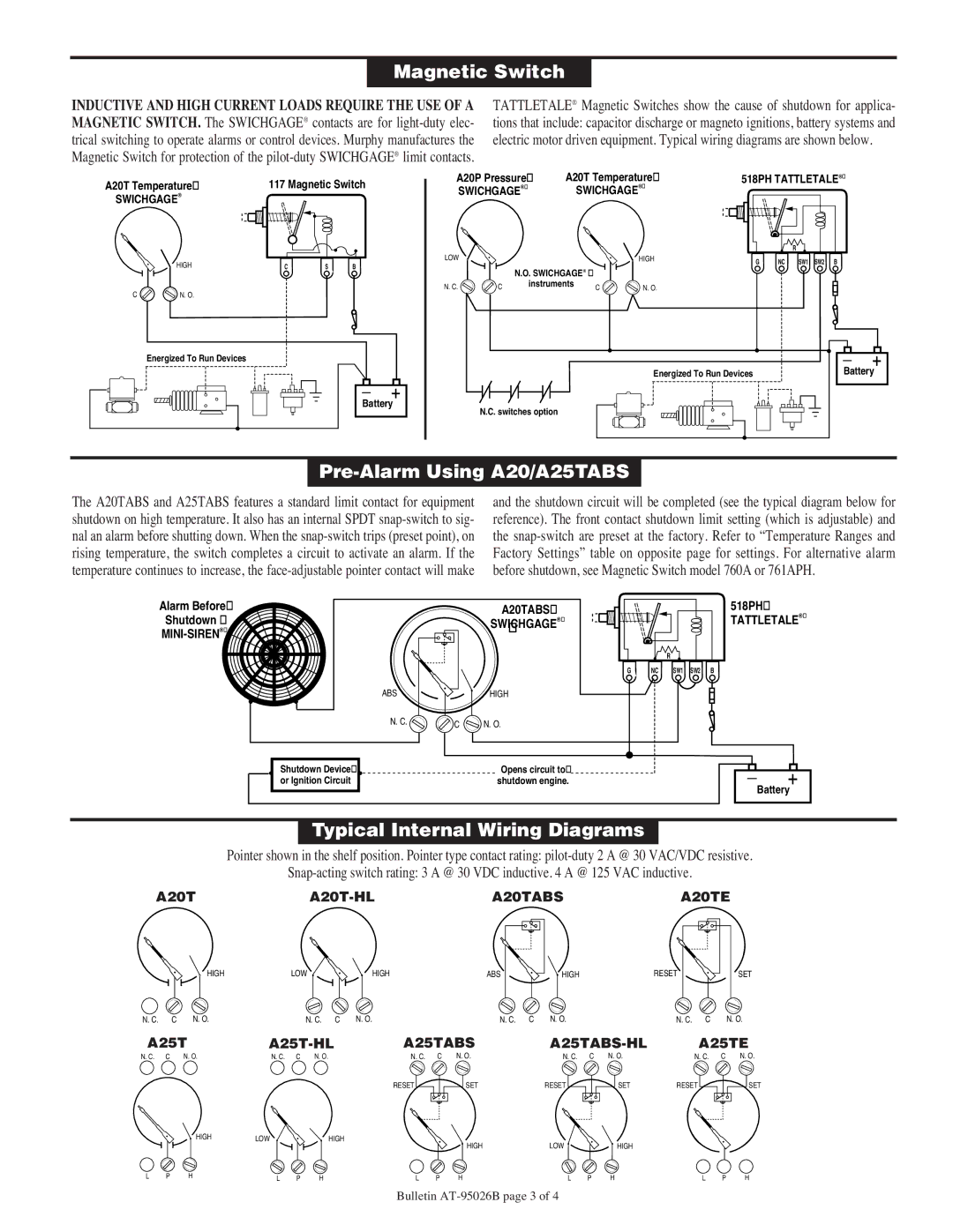
A25 Series, A20 Series specifications
The Murphy A20 Series and A25 Series are two advanced engine control and monitoring systems designed to optimize performance and enhance the productivity of various applications. Both series are recognized for their robust construction, user-friendly interfaces, and comprehensive functionalities, making them ideal choices for demanding industrial environments.The A20 Series is particularly notable for its affordability and flexibility. This system is engineered to integrate seamlessly with various engine types and monitoring setups. It features a lightweight design, making it perfect for applications where space is a premium. Key characteristics include customizable screens, allowing operators to configure display parameters according to specific needs. The A20 Series is equipped with a wide range of sensors that monitor critical engine functions like oil pressure, temperature, fuel level, and engine RPM. With advanced alarm capabilities, it enables users to respond promptly to potential issues, thus safeguarding the engine and prolonging its operational lifespan.
On the other hand, the Murphy A25 Series offers enhanced capabilities tailored for more complex applications. It boasts a more extensive display, providing a clearer interface for monitoring multiple parameters simultaneously. The A25 Series also supports robust data logging features, which are invaluable for maintenance and analysis purposes. Users can access historical data to identify trends and troubleshoot issues effectively. The A25's built-in communication protocols allow for easy integration with existing control systems, thereby enhancing flexibility and ease of use.
Both series incorporate cutting-edge technologies to improve reliability and performance. Engineered with high-quality materials and advanced electronics, they operate effectively in challenging environments. These systems are designed to function in varying temperatures and humidity levels, ensuring consistent performance under fluctuating conditions.
In conclusion, the Murphy A20 and A25 Series represent a significant advancement in engine monitoring technology. While the A20 Series is ideal for simpler applications requiring flexibility and ease of use, the A25 Series caters to those needing advanced monitoring and data logging capabilities. Together, these systems provide powerful tools for enhancing engine efficiency, safety, and operational longevity, making them essential components in modern industrial applications. Whether for construction, agriculture, or other heavy-duty landscapes, Murphy's innovative solutions stand out for their reliability and performance.

