Dimensions


A20 Series Models (typical)


A25 Series Models (typical)


2-1/4 in.

2-1/2 in.


(57 mm)

(64 mm)


PH

Y

S W I C H

G

A

G


°F


R


M

U


160

210

230


130


250


2-29/32 in.

(74 mm)


HY

S W I

C H G

A


P


G


R

°F


E

M

U


®

2-1/2 in.

(64 mm)

80

100

120

Mounting


Clamp


°C


2-1/16 in. (53 mm)

1-27/64 in.

Capillary

4 ft. (1.2 m)

Mounting hole dia.

(36 mm)

long


Contact


Adjustment


1/16 in. hex


1-1/2 in.


1/2 NPT


(38 mm)

5/8-18 U.N.F.


Adapter Nut

Sensing Bulb

Union Nut

160

210

230


130


250

80

100

120


°C


2-11/16 in. (68 mm) Mounting hole dia.

Contact

Adjustment

Mounting

Clamp

1-11/32 in.

(34 mm)

1-1/2 in.

Capillary

4 ft. (1.2 m) long

1/16 in. hex

Standard combinations. See Murphy bulletin T-8428B for optional sensing bulb, engine adaptors and capillary combinations.

1/2 NPT

Adapter Nut

(38 mm)

Sensing Bulb

5/8-18 U.N.F.

Union Nut

Temperature Ranges and Factory Settings

NOTES

1.Values in ( ) are mathematical conversions from °F to °C–they do not reflect actual second scale range. U.S.A. standard scale is °F/°C.

2.For models A20TE and A25TE; the switch trip point cannot be set at either the low or high extreme of the scale. The trip point must allow for the reset differen- tial.

3.For adjustable switch models, the trip point is adjustable only over the upper half of the scale.


Ranges Available


Hi/Lo Settings

20TABS and 25TABS Settings


Max. Temp.


Std. Settings*

Dual Scale Dial


Single Scale


Low

High


Alarm**


Shutdown


°Fahrenheit (°Celsius)


°Celsius only


°F (°C)


°F (°C)

°C only


°F (°C)

°F (°C)

°F (°C)

°C only

°F (°C)

°C only


––


185

(85)


110

(43)


32 (0)

110 (43)


100 (38)

––

110 (43)

––

32 – 120

(0 – 49)


––

32 – 160

(0 – 71)


0 – 70

215

(102)


150 (66)

66


32 (0)

150 (66)

140 (60)

60

150 (66)

66


130 – 220

(54 – 104)


45 – 100

260

(127)


210

(99)

85


160 (71)

210 (99)

200

(93)

80

210 (99)

85


130 – 250

(54 – 121)


50 – 120

310 (154)


210 (99)

97


160 (71)

210 (99)

200

(93)

95

210

(99)

100


140 – 300

(60 – 149)


60 – 140

340 (173)


275

(135)

130


200 (93)

275 (135)

265 (129)

125

275

(135)

130


160 – 320

(71 – 160)


70 – 160

370

(192)


300 (149)

150


200 (93)

300 (149)

290 (143)

145

300

(149)

150


180 – 350

(82 – 177)


––

400 (209)


330 (166)

––


240 (116)

330 (166)

320

(160)

––

330 (166)

––


300 – 440

(149 – 227)


––

500

(260)


400

(204)

––


300 (149)

400 (204)

390

(199)

––

400 (204)

––


*Standard setting for A20T, A25T, A20TE and A25TE models. ** SPDT snap-switch is the alarm switch.

Temperature Accuracy Chart

Temperature Range

Lower 1/3 of Scale

Middle 1/3 of Scale

Upper 1/3 of Scale


32 to 120°F (0 to 49°C)

± 12°F (± 6°C)

± 5°F (± 2.4°C)

± 6°F (± 3°C)


32 to 160°F (0 to 71°C)

± 20°F (± 10°C)

± 8°F (± 4.4°C)

± 7°F (± 4°C)


130 to 220°F (54 to 104°C)

± 6°F (± 3°C)

± 3°F (± 1.6°C)

± 4°F (± 2°C)


130 to 250°F (54 to 121°C)

± 9°F (± 5°C)

± 5°F (± 2.4°C)

± 4°F (± 2°C)


140 to 300°F (60 to 149°C)

± 10°F (± 5.2°C)

± 6°F (± 3°C)

± 5°F (± 2.4°C)


160 to 320°F (71 to 160°C)

± 10°F (± 5.2°C)

± 5°F (± 2.4°C)

± 5°F (± 2.4°C)


180 to 350°F (82 to 177°C)

± 12°F (± 6°C)

± 5°F (± 2.4°C)

± 5°F (± 2.4°C)


300 to 440°F (149 to 227°C)

± 9°F (± 5°C)

± 5°F (± 2.4°C)

± 4°F (± 2°C)


Maximum Temperature

MAXIMUM AMBIENT TEMPERATURE: -40° (-40°) thru 150° (66°)

RANGE

MAXIMUM PROCESS TEMPERATURE

250° (120°)

120% OF FULL SCALE

300° (140°)

350° (198°)

320° (160°)

120% OF FULL SCALE


Bulletin AT-95026B page 2 of 4

Page 2
Image 2
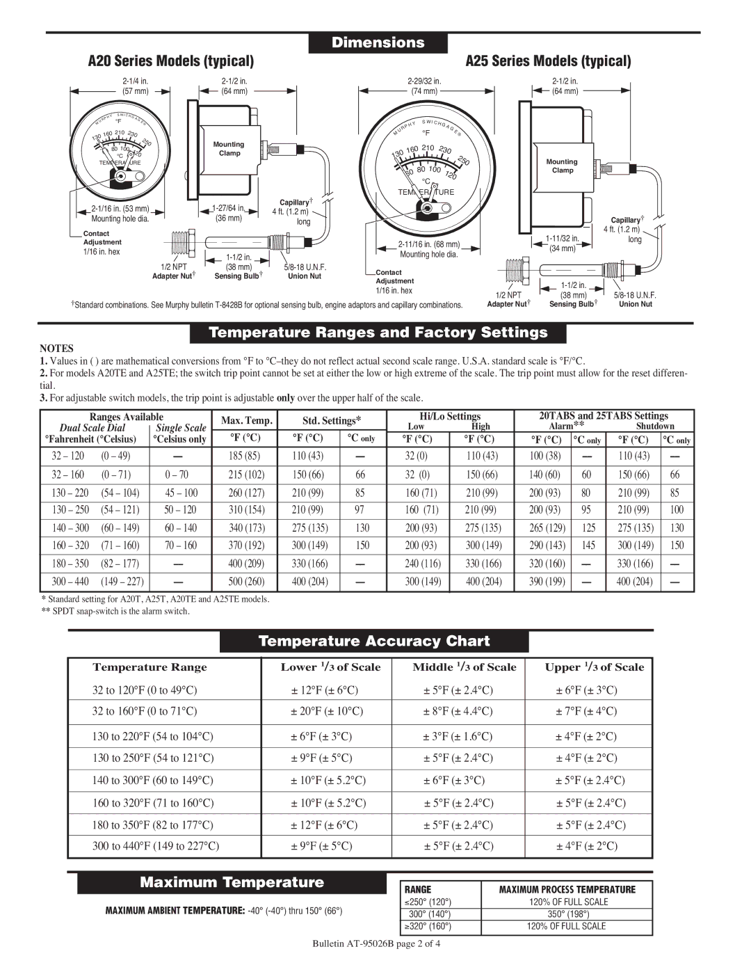
Murphy A25 Series Dimensions, Temperature Ranges and Factory Settings, Temperature Accuracy Chart, Maximum Temperature

A25 Series, A20 Series specifications

The Murphy A20 Series and A25 Series are two advanced engine control and monitoring systems designed to optimize performance and enhance the productivity of various applications. Both series are recognized for their robust construction, user-friendly interfaces, and comprehensive functionalities, making them ideal choices for demanding industrial environments.

The A20 Series is particularly notable for its affordability and flexibility. This system is engineered to integrate seamlessly with various engine types and monitoring setups. It features a lightweight design, making it perfect for applications where space is a premium. Key characteristics include customizable screens, allowing operators to configure display parameters according to specific needs. The A20 Series is equipped with a wide range of sensors that monitor critical engine functions like oil pressure, temperature, fuel level, and engine RPM. With advanced alarm capabilities, it enables users to respond promptly to potential issues, thus safeguarding the engine and prolonging its operational lifespan.

On the other hand, the Murphy A25 Series offers enhanced capabilities tailored for more complex applications. It boasts a more extensive display, providing a clearer interface for monitoring multiple parameters simultaneously. The A25 Series also supports robust data logging features, which are invaluable for maintenance and analysis purposes. Users can access historical data to identify trends and troubleshoot issues effectively. The A25's built-in communication protocols allow for easy integration with existing control systems, thereby enhancing flexibility and ease of use.

Both series incorporate cutting-edge technologies to improve reliability and performance. Engineered with high-quality materials and advanced electronics, they operate effectively in challenging environments. These systems are designed to function in varying temperatures and humidity levels, ensuring consistent performance under fluctuating conditions.

In conclusion, the Murphy A20 and A25 Series represent a significant advancement in engine monitoring technology. While the A20 Series is ideal for simpler applications requiring flexibility and ease of use, the A25 Series caters to those needing advanced monitoring and data logging capabilities. Together, these systems provide powerful tools for enhancing engine efficiency, safety, and operational longevity, making them essential components in modern industrial applications. Whether for construction, agriculture, or other heavy-duty landscapes, Murphy's innovative solutions stand out for their reliability and performance.