ADJUSTING THE SPEED SWITCH
Adjustment of the Dual Set point Speed Switch is performed when the system is otherwise operational in all respects.
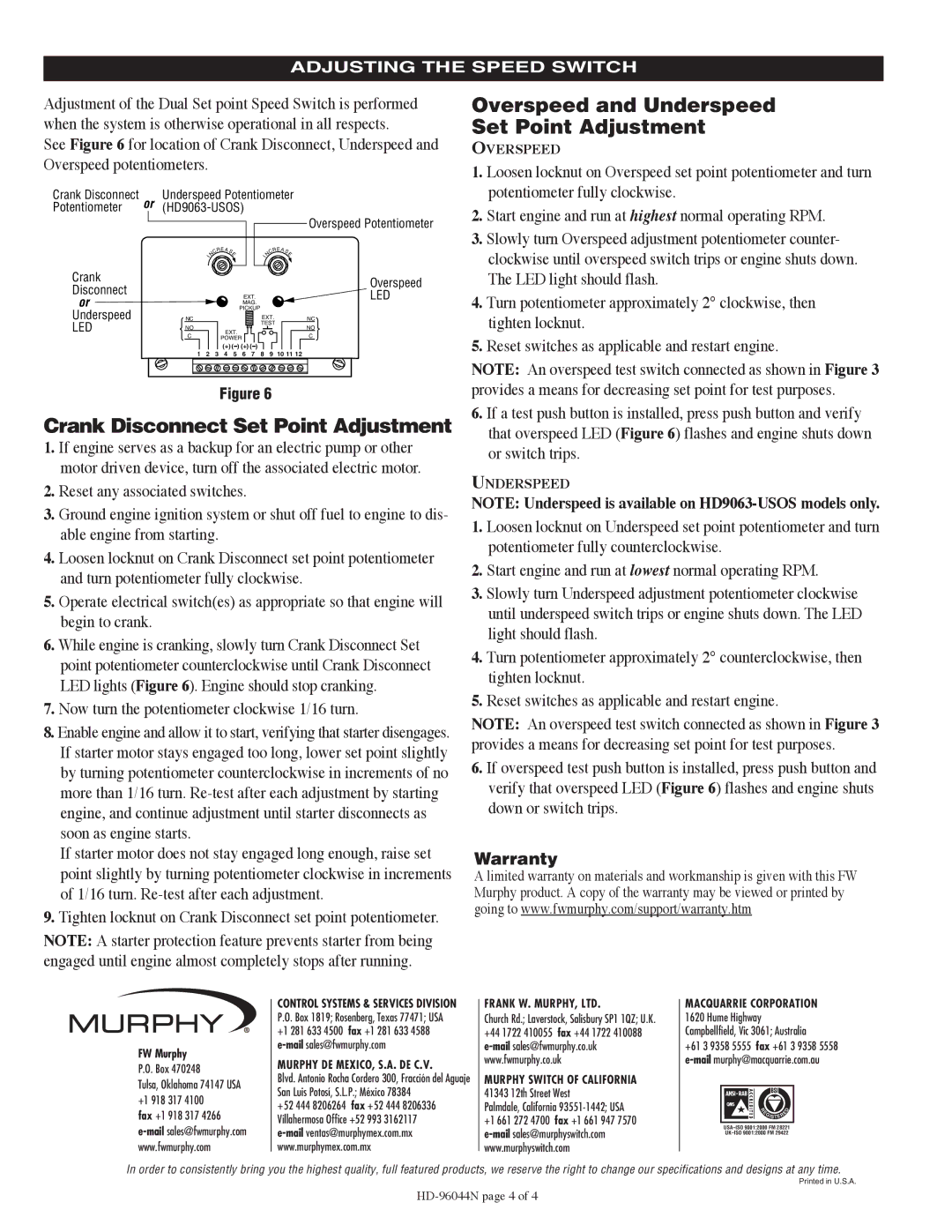
See Figure 6 for location of Crank Disconnect, Underspeed and Overspeed potentiometers.
Crank Disconnect | or | Underspeed Potentiometer | |||||||||||
Potentiometer |
|
|
|
|
|
| |||||||
|
|
|
|
|
|
|
|
|
|
|
|
| Overspeed Potentiometer |
|
|
|
| RE A | SE |
|
|
|
| RE A | SE | ||
|
|
|
| C |
|
|
|
|
| C |
| ||
|
|
| I | N |
|
|
|
|
| I | N |
|
|
Crank |
|
|
|
|
|
|
|
|
|
|
|
| Overspeed |
Disconnect |
|
|
|
|
|
|
|
|
|
|
|
| |
|
|
|
|
|
| EXT. |
|
|
|
| LED | ||
or |
|
|
|
|
|
|
|
|
|
| |||
|
|
|
|
|
| MAG. |
|
|
|
|
| ||
|
|
|
|
|
| PICKUP |
|
|
|
|
| ||
Underspeed |
| NC |
|
|
|
|
|
| EXT. |
| NC | ||
LED |
| NO |
|
| EXT. |
|
| TEST |
| NO | |||
|
|
|
|
|
|
|
|
| |||||
|
| C |
|
| POWER |
|
|
|
|
| C | ||
|
|
|
|
| (+) ( ) (+) ( ) |
|
|
|
|
| |||
|
| 1 | 2 | 3 | 4 | 5 | 6 | 7 | 8 |
| 9 | 10 11 12 | |
Figure 6
Crank Disconnect Set Point Adjustment
1.If engine serves as a backup for an electric pump or other motor driven device, turn off the associated electric motor.
2.Reset any associated switches.
3.Ground engine ignition system or shut off fuel to engine to dis- able engine from starting.
4.Loosen locknut on Crank Disconnect set point potentiometer and turn potentiometer fully clockwise.
5.Operate electrical switch(es) as appropriate so that engine will begin to crank.
6.While engine is cranking, slowly turn Crank Disconnect Set point potentiometer counterclockwise until Crank Disconnect LED lights (Figure 6). Engine should stop cranking.
7.Now turn the potentiometer clockwise 1/16 turn.
8.Enable engine and allow it to start, verifying that starter disengages. If starter motor stays engaged too long, lower set point slightly by turning potentiometer counterclockwise in increments of no more than 1/16 turn.
If starter motor does not stay engaged long enough, raise set point slightly by turning potentiometer clockwise in increments of 1/16 turn.
9.Tighten locknut on Crank Disconnect set point potentiometer.
NOTE: A starter protection feature prevents starter from being engaged until engine almost completely stops after running.
Overspeed and Underspeed
Set Point Adjustment
OVERSPEED
1.Loosen locknut on Overspeed set point potentiometer and turn potentiometer fully clockwise.
2.Start engine and run at highest normal operating RPM.
3.Slowly turn Overspeed adjustment potentiometer counter- clockwise until overspeed switch trips or engine shuts down. The LED light should flash.
4.Turn potentiometer approximately 2° clockwise, then
tighten locknut.
5.Reset switches as applicable and restart engine.
NOTE: An overspeed test switch connected as shown in Figure 3 provides a means for decreasing set point for test purposes.
6.If a test push button is installed, press push button and verify that overspeed LED (Figure 6) flashes and engine shuts down or switch trips.
UNDERSPEED
NOTE: Underspeed is available on
1.Loosen locknut on Underspeed set point potentiometer and turn potentiometer fully counterclockwise.
2.Start engine and run at lowest normal operating RPM.
3.Slowly turn Underspeed adjustment potentiometer clockwise until underspeed switch trips or engine shuts down. The LED light should flash.
4.Turn potentiometer approximately 2° counterclockwise, then tighten locknut.
5.Reset switches as applicable and restart engine.
NOTE: An overspeed test switch connected as shown in Figure 3 provides a means for decreasing set point for test purposes.
6.If overspeed test push button is installed, press push button and verify that overspeed LED (Figure 6) flashes and engine shuts down or switch trips.
Warranty
A limited warranty on materials and workmanship is given with this FW Murphy product. A copy of the warranty may be viewed or printed by going to www.fwmurphy.com/support/warranty.htm
FW Murphy
P.O. Box 470248
Tulsa, Oklahoma 74147 USA +1 918 317 4100
fax +1 918 317 4266
CONTROL SYSTEMS & SERVICES DIVISION P.O. Box 1819; Rosenberg, Texas 77471; USA +1 281 633 4500 fax +1 281 633 4588
MURPHY DE MEXICO, S.A. DE C.V.
Blvd. Antonio Rocha Cordero 300, Fracción del Aguaje San Luis Potosí, S.L.P.; México 78384
+52 444 8206264 fax +52 444 8206336 Villahermosa Office +52 993 3162117
FRANK W. MURPHY, LTD.
Church Rd.; Laverstock, Salisbury SP1 1QZ; U.K. +44 1722 410055 fax +44 1722 410088
MURPHY SWITCH OF CALIFORNIA
41343 12th Street West
Palmdale, California 93551-1442; USA
+1 661 272 4700 fax +1 661 947 7570
MACQUARRIE CORPORATION 1620 Hume Highway Campbellfield, Vic 3061; Australia
+61 3 9358 5555 fax +61 3 9358 5558
| E |
|
| D |
|
|
| ||
| R |
|
|
|
|
|
| E |
|
| GISTER |
| ||
|
|
|
|
|
In order to consistently bring you the highest quality, full featured products, we reserve the right to change our specifications and designs at any time.
Printed in U.S.A.