RTD Transmitter Installation Instructions RTDT Series Models

RTDT-96091N

Revised 01-01

Section 10

00-02-0849

Please read the following information before installing. A visual inspection of this product for damage during shipping is recommended before mounting. It is your responsibility to have a qualified person install this unit and make sure it conforms to NEC and local codes.

GENERAL INFORMATION

WARNING

BEFORE BEGINNING INSTALLATION OF THIS MURPHY PRODUCT

Disconnect all electrical power to the machine.

Make sure the machine cannot operate during installation.

Follow all safety warnings of the machine manufacturer.

Read and follow all installation instructions.

Description

The Murphy RTD transmitter is designed to accept a signal from an RTD sensing element, and to provide a linearized 4 to 20 mA output current. The output cur- rent is directly proportional to the temperature of the RTD temperature sensor. Since the temperature is converted to a current signal, voltage drops in the power supply leads to the transmitter have no effect on the integrity of the signal. As long as the transmitter has sufficient DC voltage at its terminals, it will produce a cur- rent linearly proportional to temperature. This means that the transmitter may be remote mounted but should be near the sensor, reducing the effects of noise and minimizing errors due to long leads on the RTD sensor. The RTD instruments have screw terminal connections and accept 2 or 3 wire RTD's* . They include high resolution, 24-turn zero and span potentiometers and each unit is calibrat- ed after a minimum of 48 hours burn-in and checkout time.

*Three wire RTD's compensate for leadwire resistance.

Specifications

Sensor Input: Platinum RTD 100 ohms

Output Span: 4 to 20 mA

Loop Power Supply Voltage: Typically 24 VDC; when using Loop Resistance Graph 13 – 40 VDC.

Temperature Span: 50°F (28°C) minimum; 1000°F (556°C) maximum

Calibrated Accuracy: 0.1 %

Conformity: 0.1 % of Span

Ranges: -60 to 140°F; 0 to 400°F

Ambient Temperature Limits: -30 to 165°F (-34 to 74°C)

Power Supply Effect: 0.001% volt

Current: 3.4 mA minimum; 30 mA maximum.

Upscale Burnout: Standard

Reversed Polarity Protection: Standard

Nominal Zero and Span Adjustments: ±10%

Connections: Screw Terminal

Power Supply

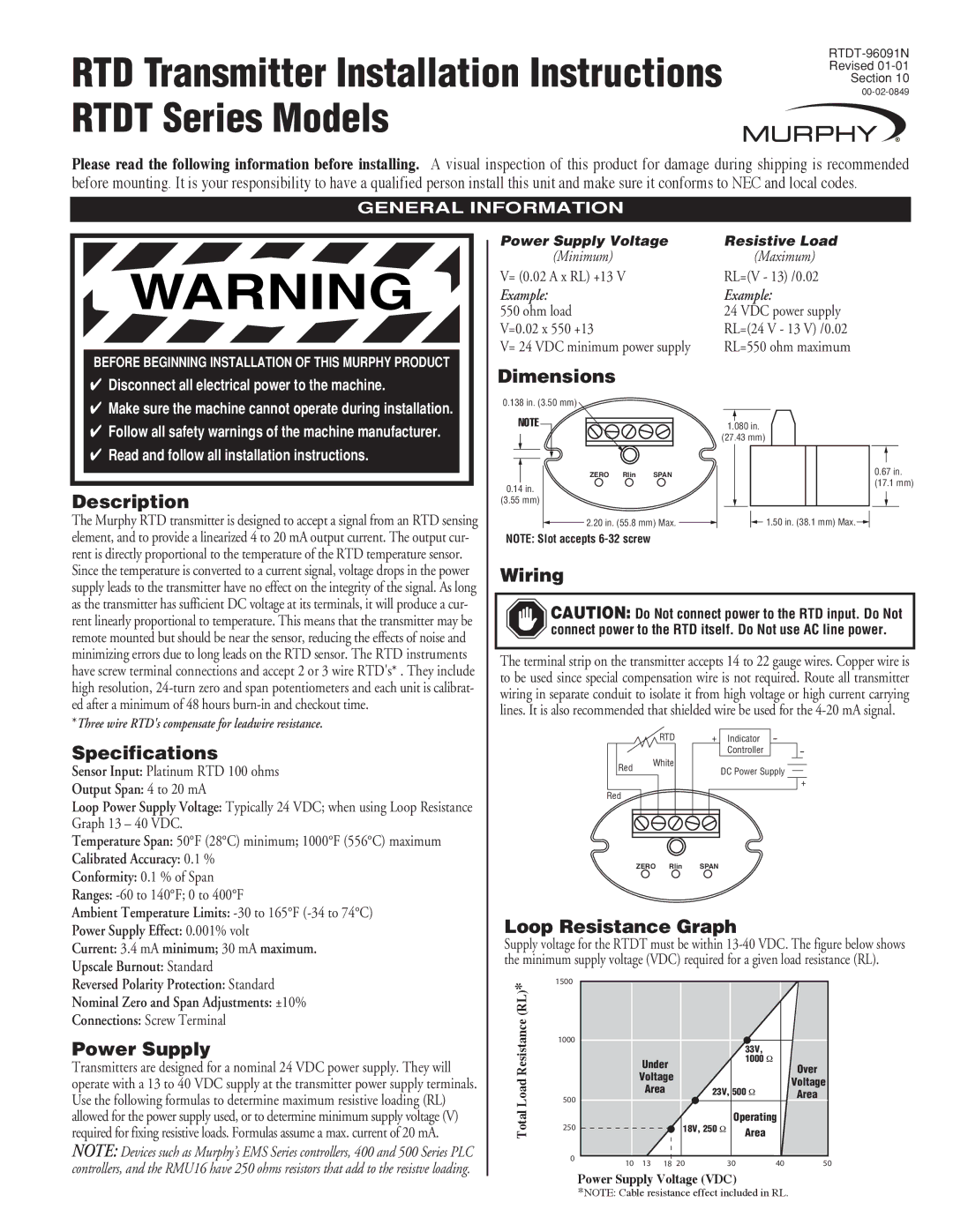
Transmitters are designed for a nominal 24 VDC power supply. They will operate with a 13 to 40 VDC supply at the transmitter power supply terminals. Use the following formulas to determine maximum resistive loading (RL) allowed for the power supply used, or to determine minimum supply voltage (V) required for fixing resistive loads. Formulas assume a max. current of 20 mA.

NOTE: Devices such as Murphy’s EMS Series controllers, 400 and 500 Series PLC controllers, and the RMU16 have 250 ohms resistors that add to the resistve loading.

Power Supply Voltage

Resistive Load

(Minimum)

(Maximum)

V= (0.02 A x RL) +13 V

RL=(V - 13) /0.02

Example:

Example:

550 ohm load

24 VDC power supply

V=0.02 x 550 +13

RL=(24 V - 13 V) /0.02

V= 24 VDC minimum power supply

RL=550 ohm maximum

Dimensions

0.138 in. (3.50 mm)


NOTE

1.080 in.


(27.43 mm)

ZERO Rlin SPAN

0.67 in.

0.14 in.

(17.1 mm)


(3.55 mm)


2.20 in. (55.8 mm) Max.

1.50 in. (38.1 mm) Max.

NOTE: Slot accepts 6-32 screw


Wiring

CAUTION: Do Not connect power to the RTD input. Do Not connect power to the RTD itself. Do Not use AC line power.

The terminal strip on the transmitter accepts 14 to 22 gauge wires. Copper wire is to be used since special compensation wire is not required. Route all transmitter wiring in separate conduit to isolate it from high voltage or high current carrying lines. It is also recommended that shielded wire be used for the 4-20 mA signal.

RTD

+ Indicator

--


Controller

--

Red

White

DC Power Supply


+

Red

ZERO Rlin SPAN

Loop Resistance Graph

Supply voltage for the RTDT must be within 13-40 VDC. The figure below shows the minimum supply voltage (VDC) required for a given load resistance (RL).

(RL)*

1500


Resistance

1000


33V,


Under


1000


Over


Load


Voltage


Voltage


Area

23V, 500


Area

500


Total

250


18V, 250


Operating


Area


0

10

13

18

20


30


40

50


Power Supply Voltage (VDC)

*NOTE: Cable resistance effect included in RL.

Page 1
Image 1
Murphy RTDT Series specifications Description, Specifications, Power Supply, Dimensions, Wiring, Loop Resistance Graph

RTDT Series specifications

The Murphy RTDT Series represents a significant advancement in the realm of industrial instrumentation and control devices, specifically designed for monitoring and displaying critical engine parameters. These robust systems are ideal for use in a variety of applications, including marine, oil and gas, power generation, and other heavy-duty environments where reliability and durability are paramount.

One of the standout features of the RTDT Series is its user-friendly interface. The devices come equipped with a bright, easy-to-read digital display that presents essential engine data, such as temperature, pressure, and RPM, in real-time. This immediate visibility allows operators to make informed decisions quickly, thereby enhancing operational safety and efficiency.

The RTDT Series utilizes advanced sensor technology to deliver accurate measurements under challenging conditions. These sensors are designed to withstand extreme temperatures and pressures, which makes them suitable for environments that traditional instruments may struggle to endure. Additionally, the devices are often equipped with built-in alarm systems that can alert users to abnormal conditions, enabling proactive maintenance and reducing the risk of equipment failure.

Connectivity is another critical aspect of the RTDT Series. Many models offer various communication options, including RS-232 and RS-485 interfaces, which facilitate integration into broader control systems. This feature not only enhances the versatility of the devices but also allows for remote monitoring and data logging, providing invaluable insights into system performance over time.

Another key characteristic of the RTDT Series is its modular design. This design allows for easy customization and scalability, meaning that operators can configure the system according to specific needs without having to invest in entirely new equipment. This adaptability is particularly beneficial in industrial settings where requirements may change frequently.

The construction of the RTDT devices also emphasizes durability. They are built with rugged materials that resist corrosion and wear, ensuring a long service life even in the harshest conditions. Such built-to-last qualities make the RTDT Series a trustworthy choice for industries where equipment uptime is critical, and maintenance costs need to be minimized.

In conclusion, the Murphy RTDT Series stands out due to its impressive features, including user-friendly interfaces, advanced sensor technology, versatile connectivity options, modular design, and robust construction. These characteristics make it an invaluable tool for operators who require reliable and precise monitoring solutions in demanding environments. Whether in marine applications or oil and gas operations, the RTDT Series delivers performance, durability, and the flexibility needed for today’s industrial challenges.