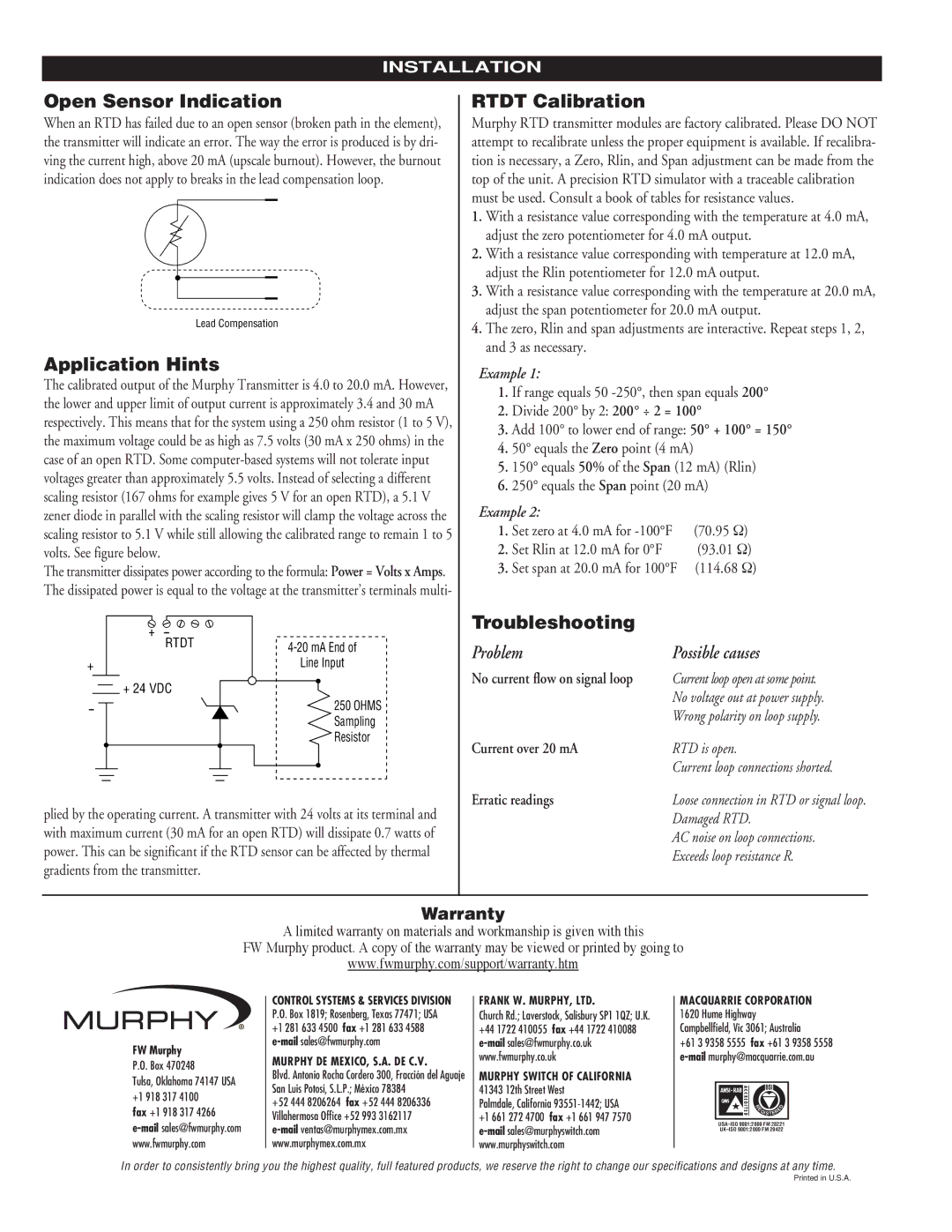
RTDT Series specifications
The Murphy RTDT Series represents a significant advancement in the realm of industrial instrumentation and control devices, specifically designed for monitoring and displaying critical engine parameters. These robust systems are ideal for use in a variety of applications, including marine, oil and gas, power generation, and other heavy-duty environments where reliability and durability are paramount.One of the standout features of the RTDT Series is its user-friendly interface. The devices come equipped with a bright, easy-to-read digital display that presents essential engine data, such as temperature, pressure, and RPM, in real-time. This immediate visibility allows operators to make informed decisions quickly, thereby enhancing operational safety and efficiency.
The RTDT Series utilizes advanced sensor technology to deliver accurate measurements under challenging conditions. These sensors are designed to withstand extreme temperatures and pressures, which makes them suitable for environments that traditional instruments may struggle to endure. Additionally, the devices are often equipped with built-in alarm systems that can alert users to abnormal conditions, enabling proactive maintenance and reducing the risk of equipment failure.
Connectivity is another critical aspect of the RTDT Series. Many models offer various communication options, including RS-232 and RS-485 interfaces, which facilitate integration into broader control systems. This feature not only enhances the versatility of the devices but also allows for remote monitoring and data logging, providing invaluable insights into system performance over time.
Another key characteristic of the RTDT Series is its modular design. This design allows for easy customization and scalability, meaning that operators can configure the system according to specific needs without having to invest in entirely new equipment. This adaptability is particularly beneficial in industrial settings where requirements may change frequently.
The construction of the RTDT devices also emphasizes durability. They are built with rugged materials that resist corrosion and wear, ensuring a long service life even in the harshest conditions. Such built-to-last qualities make the RTDT Series a trustworthy choice for industries where equipment uptime is critical, and maintenance costs need to be minimized.
In conclusion, the Murphy RTDT Series stands out due to its impressive features, including user-friendly interfaces, advanced sensor technology, versatile connectivity options, modular design, and robust construction. These characteristics make it an invaluable tool for operators who require reliable and precise monitoring solutions in demanding environments. Whether in marine applications or oil and gas operations, the RTDT Series delivers performance, durability, and the flexibility needed for today’s industrial challenges.

