BASIC OPERATION
ST8
1.Apply power to the ST8 TATTLETALE® (terminals 13 and 14).
2.The “POWER ON” and “RUN” LED light will switch On. The “POWER ON” LED indicates power has been applied to the ST8. The “RUN” LED indicates the internal relay is in the operating mode.
3.The lockout time delay during startup will begin timing. Sensors with lockout time delay selected (see Setting Lockout Switches below) will not trip alarm or shutdown circuit until time delay times out
4.The 8 Red shutdown LEDs are for shutdown indication (see Figure 6).
5.When a shutdown signal is received from a SWICHGAGE®, the shutdown LED will light and internal shutdown relay will switch to activate a shutdown device (see Typical Wiring page 3). All other shutdown sensor inputs are locked out.
6.Shutdown LED will remain on even if conditions return to normal. To clear the LED, power must be removed or push button reset is operated.
Setting Lockout Switches
Lockout switches allow you to lockout shutdown/alarm sensors during startup. For instance, on a pressure SWICHGAGE®, the lockout time
delay allows time for pressure to build up thus lifting the pointer off the | ||||||||||||||||||
low limit contact. If the lockout time delay is not set the TATTLE- | ||||||||||||||||||
TALE® will initiate the shutdown/alarm sequence. | ||||||||||||||||||
Each sensor input on the ST8 has a lockout |
|
|
|
|
|
|
|
|
|
|
|
|
|
|
|
|
|
|
time delay at startup with a length of 25 to |
|
|
| Lockout | ||||||||||||||
35 seconds. |
|
|
| |||||||||||||||
|
| Switches | ||||||||||||||||
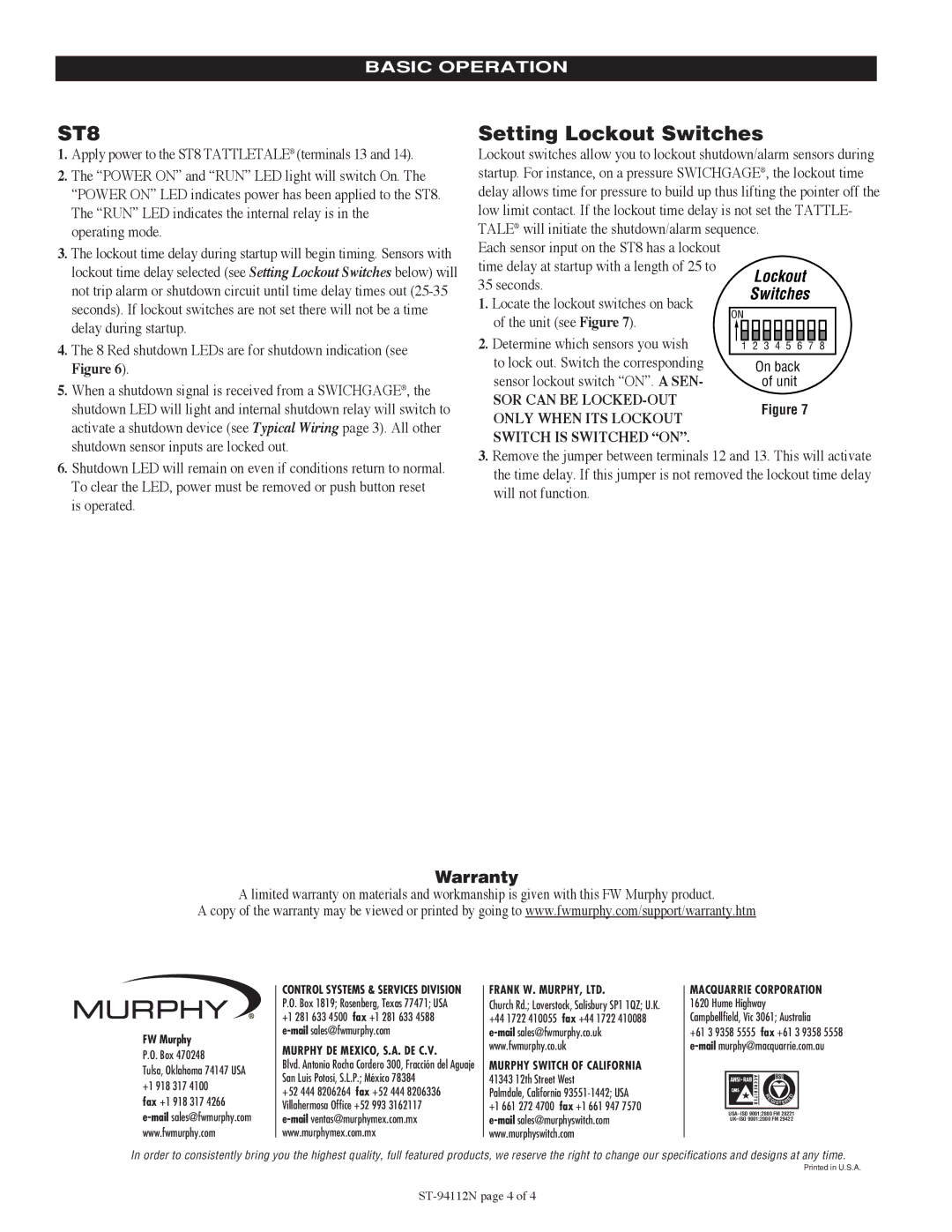
1. Locate the lockout switches on back |
|
| ||||||||||||||||
|
|
|
|
|
|
|
|
|
|
|
|
|
|
|
|
|
| |
of the unit (see Figure 7). | ON |
| ||||||||||||||||
|
|
|
|
|
|
|
|
|
|
|
|
|
|
|
|
|
| |
2. Determine which sensors you wish to lock out. Switch the corresponding sensor lockout switch “ON”. A SEN-
SOR CAN BE
ONLY WHEN ITS LOCKOUT
SWITCH IS SWITCHED “ON”.
3.Remove the jumper between terminals 12 and 13. This will activate the time delay. If this jumper is not removed the lockout time delay will not function.
Warranty
A limited warranty on materials and workmanship is given with this FW Murphy product.
A copy of the warranty may be viewed or printed by going to www.fwmurphy.com/support/warranty.htm
FW Murphy
P.O. Box 470248
Tulsa, Oklahoma 74147 USA +1 918 317 4100
fax +1 918 317 4266
CONTROL SYSTEMS & SERVICES DIVISION P.O. Box 1819; Rosenberg, Texas 77471; USA +1 281 633 4500 fax +1 281 633 4588
MURPHY DE MEXICO, S.A. DE C.V.
Blvd. Antonio Rocha Cordero 300, Fracción del Aguaje San Luis Potosí, S.L.P.; México 78384
+52 444 8206264 fax +52 444 8206336 Villahermosa Office +52 993 3162117
FRANK W. MURPHY, LTD.
Church Rd.; Laverstock, Salisbury SP1 1QZ; U.K. +44 1722 410055 fax +44 1722 410088
MURPHY SWITCH OF CALIFORNIA
41343 12th Street West
Palmdale, California 93551-1442; USA
+1 661 272 4700 fax +1 661 947 7570
MACQUARRIE CORPORATION 1620 Hume Highway Campbellfield, Vic 3061; Australia
+61 3 9358 5555 fax +61 3 9358 5558
| E |
|
| D |
|
|
| ||
| R |
|
|
|
|
|
| E |
|
| GISTER |
| ||
|
|
|
|
|
In order to consistently bring you the highest quality, full featured products, we reserve the right to change our specifications and designs at any time.
Printed in U.S.A.