CONNECTIONS & FACILITIES
REMOTE CONTROL
REMOTE CONTROL
Buttons on the remote control with
As the remote control uses an invisible
Pressing button numbers 1, 2, 3 or 4 selects a corresponding amplifier input.
| 1 | 2 | 3 | 4 |
|
| |
|
|
|
|
|
|
|
|
|
|
|
|
|
|
|
|
|
|
|
|
|
|
|
|
|
|
|
|
|
|
|
|
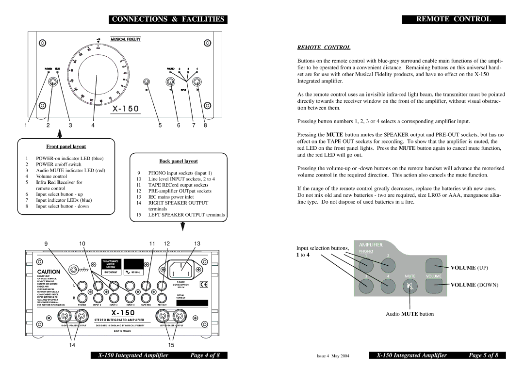
Front panel layout
1
2POWER on/off switch
3Audio MUTE indicator LED (red)
4Volume control
5Infra Red Receiver for remote control
6Input select button - up
7Input indicator LEDs (blue)
8Input select button - down
5 6 7 8
Back panel layout
9PHONO input sockets (input 1)
10 Line level INPUT sockets, 2 to 4
11 TAPE RECord output sockets
12
13 IEC mains power inlet
14 RIGHT SPEAKER OUTPUT terminals
15 LEFT SPEAKER OUTPUT terminals
Pressing the MUTE button mutes the SPEAKER output and
Pressing the
If the range of the remote control greatly decreases, replace the batteries with new ones. Do not mix old and new batteries - two are required, size LR03 or AAA, manganese alka- line type. Do not dispose of used batteries in a fire.
| 9 |
| 10 |
| 11 | 12 | 13 |
|
|
|
|
|
|
|
|
|
|
|
|
|
|
|
|
|
|
|
|
|
|
CAUTION | IMPORTANT | 50/60Hz |
|
MOUNT UNIT |
|
|
|
ON SOLID SURFACE. |
|
|
|
DO NOT REMOVE |
|
| POWER |
SCREWS OR COVERS |
|
| |
|
| CONSUMPTION | |
UNDER ANY |
|
| |
|
| 320 W | |
CIRCUMSTANCES. |
|
|
|
NO USER SERVICEABLE |
|
|
|
COMPONENTS INSIDE. |
|
| SERIAL |
REFER SERVICING TO |
|
| NUMBER |
QUALIFIED ENGINEER. |
|
| |
|
|
| |
SEE OWNERS MANUAL |
|
|
|
FOR FURTHER INFORMATION. |
|
|
|
| X - 1 5 0 |
| |
| S T E R EO INTEGRATED AMPLIFIER |
| |
RIGHT SPEAKER OUTPUT | DESIGNED IN ENGLAND BY MUSICAL FIDELITY | LEFT SPEAKER OUTPUT | |
| BUILT IN TAIWAN |
|
|
1415
Input selection buttons,
1 to 4
![]()
![]()
![]()
![]() VOLUME (UP)
VOLUME (UP)
![]()
![]()
![]() VOLUME (DOWN)
VOLUME (DOWN)
Audio MUTE button
Page 4 of 8 |
Issue 4 May 2004 | Page 5 of 8 |