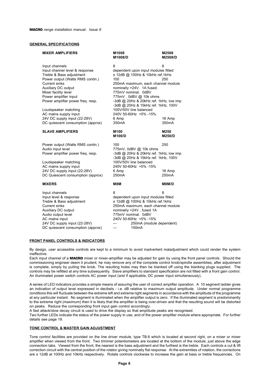
M250/SD, M1008/D, M1008, M100/S, M250/S specifications
The Mustang M1008, M2508, M250/SD, M/8M, and M100/S are a series of versatile aircraft designed to meet various operational needs in both civilian and military environments. These aircraft are known for their robust performance, advanced technologies, and user-friendly characteristics that make them suitable for tasks ranging from logistics to surveillance.One of the main features of the Mustang M1008 is its efficient powerplant. It is equipped with a high-performance engine that delivers exceptional thrust and speed while maintaining fuel efficiency. This capability allows for extended ranges and longer flight durations, making it an ideal choice for long-haul missions. The M1008 has a spacious cabin designed for cargo transport, accommodating various payloads, and can be easily modified for different roles.
The M2508 variant incorporates advanced avionics and navigation systems, improving situational awareness for pilots. Its cutting-edge cockpit design offers a user-friendly interface, enhancing pilot control and reducing workload during complex operations. Additionally, the M2508 features enhanced safety systems, including redundant controls and automated flight systems, ensuring mission reliability even in challenging conditions.
The M250/SD model focuses on surveillance and reconnaissance applications. It is equipped with sophisticated imaging and sensor technologies that allow for real-time data collection and analysis. This capability is vital for military operations, providing ground forces with actionable intelligence and improving operational effectiveness. The M250/SD’s ability to adapt to different sensor suites makes it a valuable asset in various mission profiles.
The M/8M variant is notable for its versatility in various terrains. Its rugged design allows for impressive off-road capabilities, making it suitable for operations in remote and challenging environments. With reinforced landing gear and a spacious cargo bay, the M/8M can handle rough landings and transport heavy equipment, crucial for logistical support in the field.
Lastly, the M100/S emphasizes speed and agility, catering to urgent transport needs. This aircraft can operate in tighter spaces, enabling it to access locations that larger aircraft cannot. Its streamlined design minimizes drag, resulting in higher speeds and lower fuel consumption.
Overall, the Mustang M1008/D, M2508, M250/SD, M/8M, and M100/S deliver a combination of performance, versatility, and advanced technology, making them formidable options in their respective roles. Whether for logistics, surveillance, or both, these aircraft provide solutions that meet the demands of modern aviation.
