FIGURE 7
3F Manual Inflator
MD3085 Manual Inflator
|
|
|
|
|
| Cylinder |
|
|
|
|
|
|
|
| |
|
|
|
|
|
| Step 2 |
|
|
|
|
|
| |||
|
|
|
|
|
| Sensor | Ring |
|
|
|
|
|
| Step 3 |
|
|
|
|
|
|
| Bayonet |
|
|
|
|
|
|
| Tab |
|
|
|
|
|
|
|
| |
|
|
|
|
|
| Step 4 | |
|
|
|
|
|
| ||
|
|
|
|
|
| Step 3 | |
Service |
|
|
| Lever | |||
|
|
| |||||
Indicator |
|
|
|
|
| Step 4 | |
Step 5 |
|
|
| ||||
|
|
|
|
| |||
Service Indicator
If green, unit is operable
If red, stop and service unit
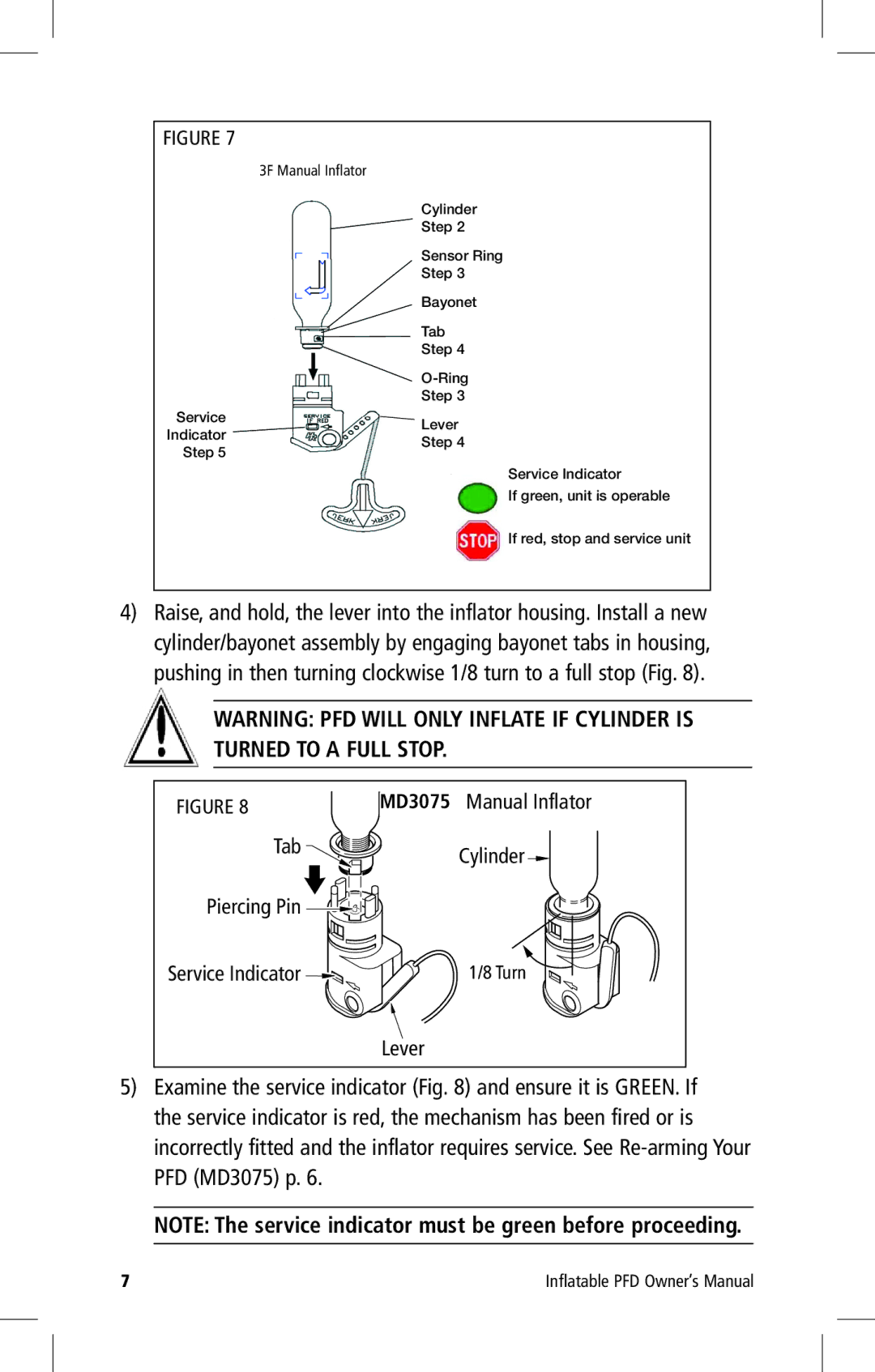
4)Raise, and hold, the lever into the inflator housing. Install a new cylinder/bayonet assembly by engaging bayonet tabs in housing, pushing in then turning clockwise 1/8 turn to a full stop (Fig. 8).
WARNING: PFD WILL ONLY INFLATE IF CYLINDER IS TURNED TO A FULL STOP.
Figure 8 | MD3075 Manual Inflator |
Tab | Cylinder |
| |
Piercing Pin |
|
Service Indicator | 1/8 Turn |
Lever
5)Examine the service indicator (Fig. 8) and ensure it is GREEN. If the service indicator is red, the mechanism has been fired or is incorrectly fitted and the inflator requires service. See
NOTE: The service indicator must be green before proceeding.
7 | Inflatable PFD Owner’s Manual |