CONTROLS AND CONNECTIONS
(34)(35)
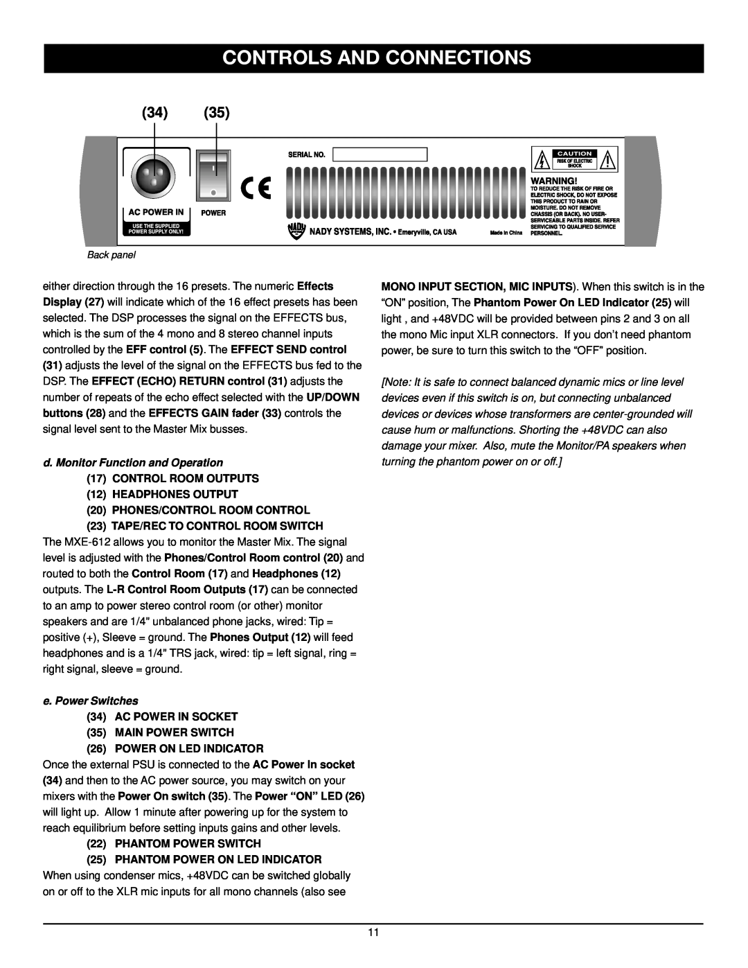
Back panel
either direction through the 16 presets. The numeric Effects Display (27) will indicate which of the 16 effect presets has been selected. The DSP processes the signal on the EFFECTS bus, which is the sum of the 4 mono and 8 stereo channel inputs controlled by the EFF control (5). The EFFECT SEND control
(31)adjusts the level of the signal on the EFFECTS bus fed to the DSP. The EFFECT (ECHO) RETURN control (31) adjusts the number of repeats of the echo effect selected with the UP/DOWN buttons (28) and the EFFECTS GAIN fader (33) controls the signal level sent to the Master Mix busses.
d. Monitor Function and Operation
(17)CONTROL ROOM OUTPUTS
(12)HEADPHONES OUTPUT
(20)PHONES/CONTROL ROOM CONTROL
(23)TAPE/REC TO CONTROL ROOM SWITCH
The
e. Power Switches
(34)AC POWER IN SOCKET
(35)MAIN POWER SWITCH
(26) POWER ON LED INDICATOR
MONO INPUT SECTION, MIC INPUTS). When this switch is in the “ON” position, The Phantom Power On LED Indicator (25) will light , and +48VDC will be provided between pins 2 and 3 on all the mono Mic input XLR connectors. If you don’t need phantom power, be sure to turn this switch to the “OFF” position.
[Note: It is safe to connect balanced dynamic mics or line level devices even if this switch is on, but connecting unbalanced devices or devices whose transformers are
Once the external PSU is connected to the AC Power In socket
(34)and then to the AC power source, you may switch on your mixers with the Power On switch (35). The Power “ON” LED (26)
will light up. Allow 1 minute after powering up for the system to reach equilibrium before setting inputs gains and other levels.
(22) PHANTOM POWER SWITCH
(25) PHANTOM POWER ON LED INDICATOR
When using condenser mics, +48VDC can be switched globally on or off to the XLR mic inputs for all mono channels (also see
11