FRONT & REAR CONNECTIONS
(1) (2) (6) (10)
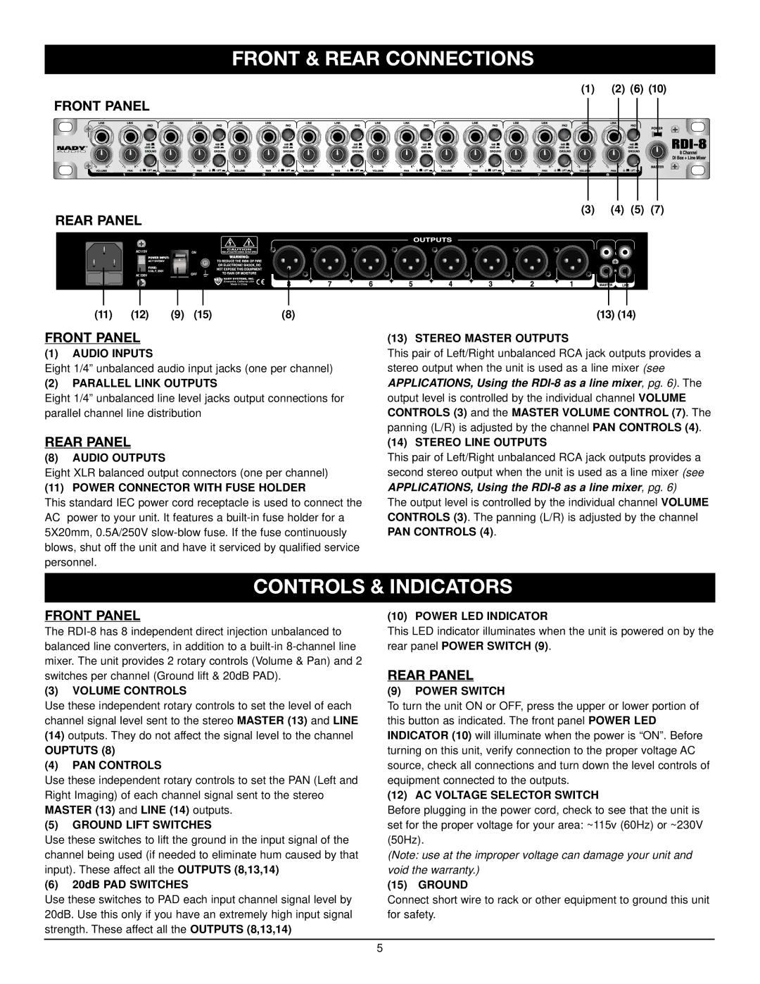
FRONT PANEL
(3) (4) (5) (7)
REAR PANEL
(11) | (12) | (9) | (15) | (8) |
FRONT PANEL
(1)AUDIO INPUTS
Eight 1/4” unbalanced audio input jacks (one per channel)
(2)PARALLEL LINK OUTPUTS
Eight 1/4” unbalanced line level jacks output connections for parallel channel line distribution
(13) (14)
(13) STEREO MASTER OUTPUTS
This pair of Left/Right unbalanced RCA jack outputs provides a stereo output when the unit is used as a line mixer (see
APPLICATIONS, Using the RDI-8 as a line mixer, pg. 6). The
output level is controlled by the individual channel VOLUME CONTROLS (3) and the MASTER VOLUME CONTROL (7). The panning (L/R) is adjusted by the channel PAN CONTROLS (4).
REAR PANEL
(8)AUDIO OUTPUTS
Eight XLR balanced output connectors (one per channel)
(11) POWER CONNECTOR WITH FUSE HOLDER
This standard IEC power cord receptacle is used to connect the AC power to your unit. It features a
(14) STEREO LINE OUTPUTS
This pair of Left/Right unbalanced RCA jack outputs provides a second stereo output when the unit is used as a line mixer (see APPLICATIONS, Using the
The output level is controlled by the individual channel VOLUME CONTROLS (3). The panning (L/R) is adjusted by the channel PAN CONTROLS (4).
CONTROLS & INDICATORS
FRONT PANEL
The
(3)VOLUME CONTROLS
Use these independent rotary controls to set the level of each channel signal level sent to the stereo MASTER (13) and LINE
(14)outputs. They do not affect the signal level to the channel
OUPTUTS (8)
(4)PAN CONTROLS
Use these independent rotary controls to set the PAN (Left and Right Imaging) of each channel signal sent to the stereo MASTER (13) and LINE (14) outputs.
(5)GROUND LIFT SWITCHES
Use these switches to lift the ground in the input signal of the channel being used (if needed to eliminate hum caused by that input). These affect all the OUTPUTS (8,13,14)
(6)20dB PAD SWITCHES
Use these switches to PAD each input channel signal level by 20dB. Use this only if you have an extremely high input signal strength. These affect all the OUTPUTS (8,13,14)
(10) POWER LED INDICATOR
This LED indicator illuminates when the unit is powered on by the rear panel POWER SWITCH (9).
REAR PANEL
(9)POWER SWITCH
To turn the unit ON or OFF, press the upper or lower portion of this button as indicated. The front panel POWER LED INDICATOR (10) will illuminate when the power is “ON”. Before turning on this unit, verify connection to the proper voltage AC source, check all connections and turn down the level controls of equipment connected to the outputs.
(12) AC VOLTAGE SELECTOR SWITCH
Before plugging in the power cord, check to see that the unit is set for the proper voltage for your area: ~115v (60Hz) or ~230V (50Hz).
(Note: use at the improper voltage can damage your unit and void the warranty.)
(15) GROUND
Connect short wire to rack or other equipment to ground this unit for safety.
5