TMP-3 specifications
The Nady Systems TMP-3 is a versatile and innovative microphone preamp designed to cater to the needs of musicians, recording engineers, and audio professionals. This compact and portable unit is particularly appreciated for its exceptional audio quality and user-friendly features, making it a popular choice among those who seek to enhance their sound recording capabilities.One of the standout features of the TMP-3 is its dual-channel design, allowing users to connect two microphones or instruments simultaneously. This flexibility is invaluable in various settings, enabling users to capture multiple audio sources without the need for additional equipment. The preamp delivers a seamless transition between input sources, ensuring optimal performance in both studio and live environments.
The TMP-3 employs advanced analog technology that ensures a clean and natural sound reproduction. It is engineered to handle high SPL (Sound Pressure Levels), making it suitable for a wide range of applications, from professional studio recordings to live sound reinforcement. With a low-noise circuitry, the TMP-3 significantly minimizes unwanted background noise, providing a pristine audio experience.
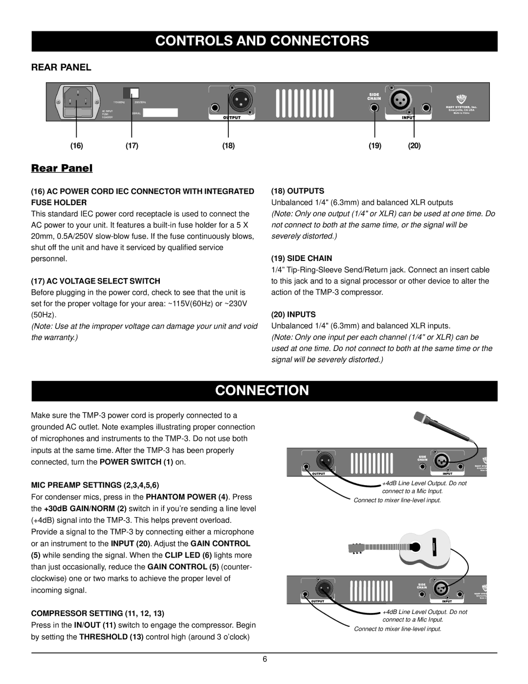
Another notable feature of the TMP-3 is its integrated phantom power capability, which allows users to power condenser microphones directly from the unit. This built-in 48V phantom power source eliminates the need for external power supplies, making the TMP-3 a highly portable solution for on-the-go recording. Additionally, the preamp includes a 1/4" output, ensuring compatibility with various audio interfaces and mixers.
The lightweight and compact design of the TMP-3 further enhances its appeal, making it easy to transport to gigs, rehearsals, or studio sessions. The rugged construction ensures durability, allowing the unit to withstand the rigors of frequent use. Its intuitive layout ensures that users can quickly adjust settings, making it accessible even for those who may be new to audio equipment.
In summary, the Nady Systems TMP-3 microphone preamp stands out for its dual-channel capabilities, exceptional sound quality, and portability. With features such as phantom power, low noise circuitry, and a durable design, it caters to a wide array of audio recording needs, making it an excellent investment for both amateurs and seasoned professionals alike. Whether for studio work or live performances, the TMP-3 continues to be a reliable choice for enhancing audio production.

