38
44
43
36 | 41 |
37
42 | 40 | 39 | 45 |
|
|
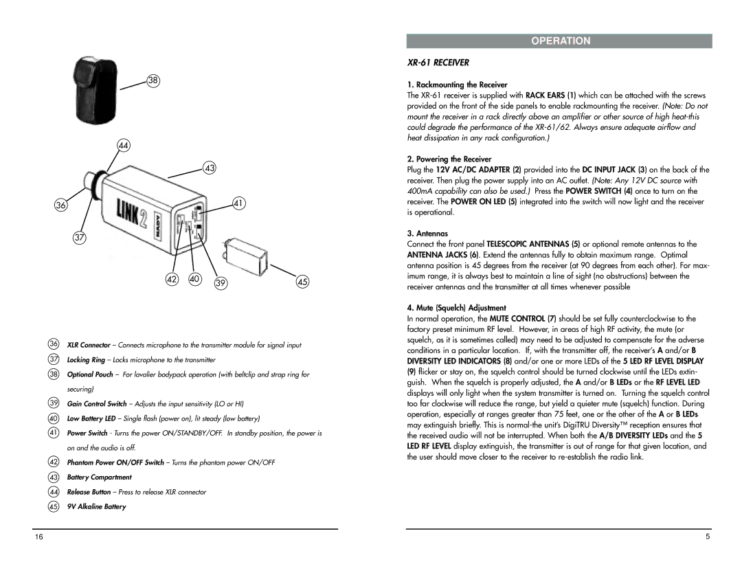
36XLR Connector – Connects microphone to the transmitter module for signal input
37Locking Ring – Locks microphone to the transmitter
38Optional Pouch – For lavalier bodypack operation (with beltclip and strap ring for securing)
39Gain Control Switch – Adjusts the input sensitivity (LO or HI)
40Low Battery LED – Single flash (power on), lit steady (low battery)
41Power Switch - Turns the power ON/STANDBY/OFF. In standby position, the power is on and the audio is off.
42Phantom Power ON/OFF Switch – Turns the phantom power ON/OFF
43Battery Compartment
44Release Button – Press to release XLR connector
459V Alkaline Battery
OPERATION
XR-61 RECEIVER
1. Rackmounting the Receiver
The
2. Powering the Receiver
Plug the 12V AC/DC ADAPTER (2) provided into the DC INPUT JACK (3) on the back of the receiver. Then plug the power supply into an AC outlet. (Note: Any 12V DC source with 400mA capability can also be used.) Press the POWER SWITCH (4) once to turn on the receiver. The POWER ON LED (5) integrated into the switch will now light and the receiver is operational.
3. Antennas
Connect the front panel TELESCOPIC ANTENNAS (5) or optional remote antennas to the ANTENNA JACKS (6). Extend the antennas fully to obtain maximum range. Optimal antenna position is 45 degrees from the receiver (at 90 degrees from each other). For max- imum range, it is always best to maintain a line of sight (no obstructions) between the receiver antennas and the transmitter at all times whenever possible
4. Mute (Squelch) Adjustment
In normal operation, the MUTE CONTROL (7) should be set fully counterclockwise to the factory preset minimum RF level. However, in areas of high RF activity, the mute (or squelch, as it is sometimes called) may need to be adjusted to compensate for the adverse conditions in a particular location. If, with the transmitter off, the receiver’s A and/or B DIVERSITY LED INDICATORS (8) and/or one or more LEDs of the 5 LED RF LEVEL DISPLAY
(9)flicker or stay on, the squelch control should be turned clockwise until the LEDs extin- guish. When the squelch is properly adjusted, the A and/or B LEDs or the RF LEVEL LED displays will only light when the system transmitter is turned on. Turning the squelch control too far clockwise will reduce the range, but yield a quieter mute (squelch) function. During operation, especially at ranges greater than 75 feet, one or the other of the A or B LEDs may extinguish briefly. This is
16 | 5 |