Manuals
/
Napoleon Grills
/
Household Appliance
/
Indoor Furnishings
Napoleon Grills
WF 9, WF9ST, WF 18, WF 6
manual
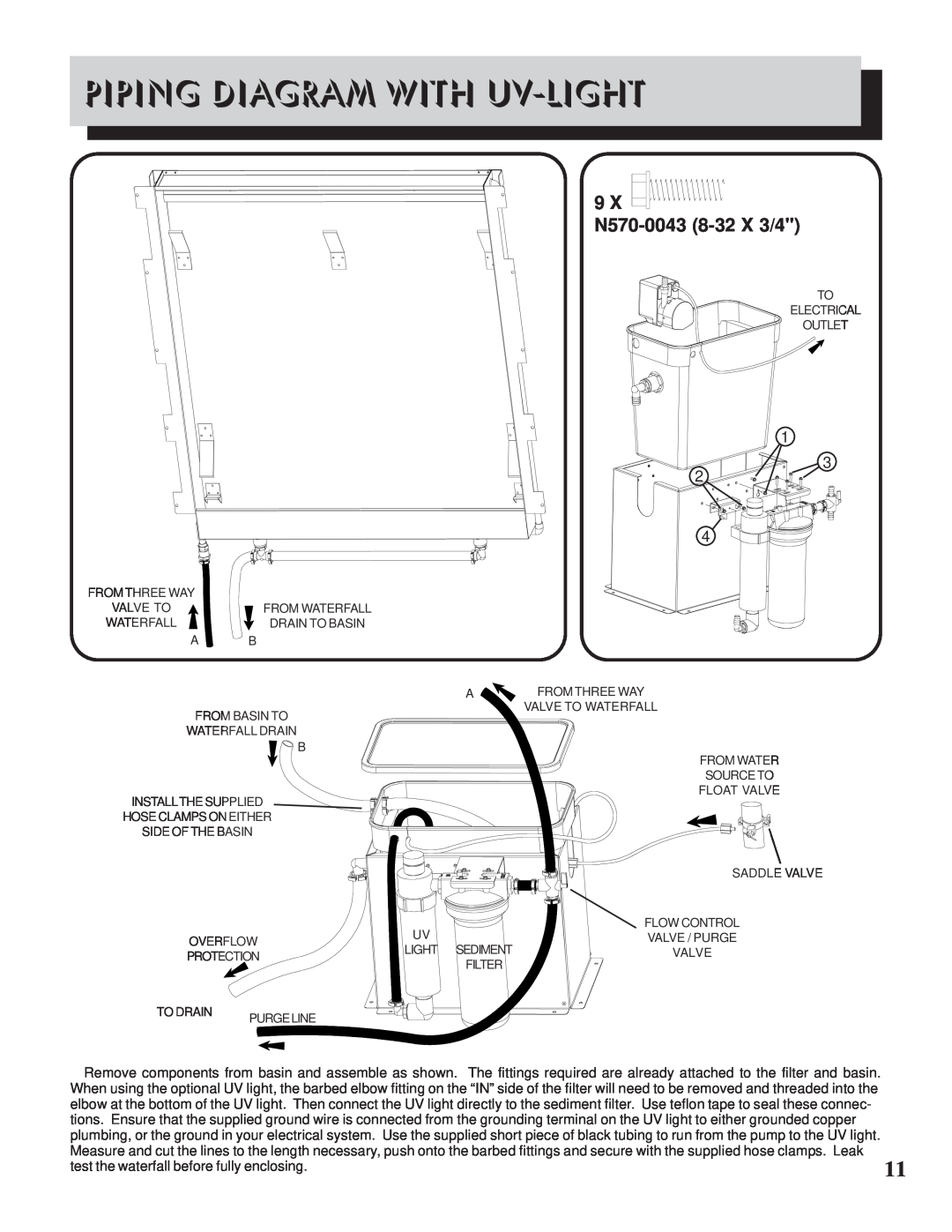
Piping Diagram With Uv-Light, 9 N570-0043 8-32X 3/4
Models:
WF 9
WF 6
WF 18
WF9ST
1
11
13
13
Download
13 pages
41.5 Kb
6
7
8
9
10
11
12
13
Troubleshooting
Specifications
Install
Parts list
Piping Diagram With Uv-Light
Cleaning And Maintenance
Ordering Replacement Parts
Page 11
Image 11
Page 10
Page 12
Page 11
Image 11
Page 10
Page 12
Contents
THAT PURIFY AND HUMIDIFY THE AIR
WF 6/9/18 WF9ST
SERIAL / SÉRIE#
DECORATIVE INDOOR WATERFALLS
CONDITIONS AND LIMITATIONS
NAPOLEON WATERFALL PRESIDENTS WARRANTY
appropriate location
installation Tools and materials required
indoor air quality
ELECTRICAL REQUIREMENTS
water
WATER PUMPS
WATERFALL SURFACE MATERIALS
INSTALLATION
CLEANING AND MAINTENANCE
Possible Causes
TROUBLESHOOTING
Problem
Solution
ORDERING REPLACEMENT PARTS
FRAMING SPECIFICATIONS
6 N570-0043 8-32X 3/4
PIPING DIAGRAM WITHOUT UV LIGHT
9 N570-0043 8-32X 3/4
PIPING DIAGRAM WITH UV-LIGHT
PARTS LIST
WATERFALL SURFACE INSTALLATION
PARTS DIAGRAM
Top
Page
Image
Contents