Manuals
/
National
/
Computer Equipment
/
Computer Hardware
National
LM95235
manual
Introduction, 1.1Block Diagram
Models:
LM95235
1
4
15
15
Download
15 pages
5.27 Kb
1
2
3
4
5
6
7
8
Specs
Install
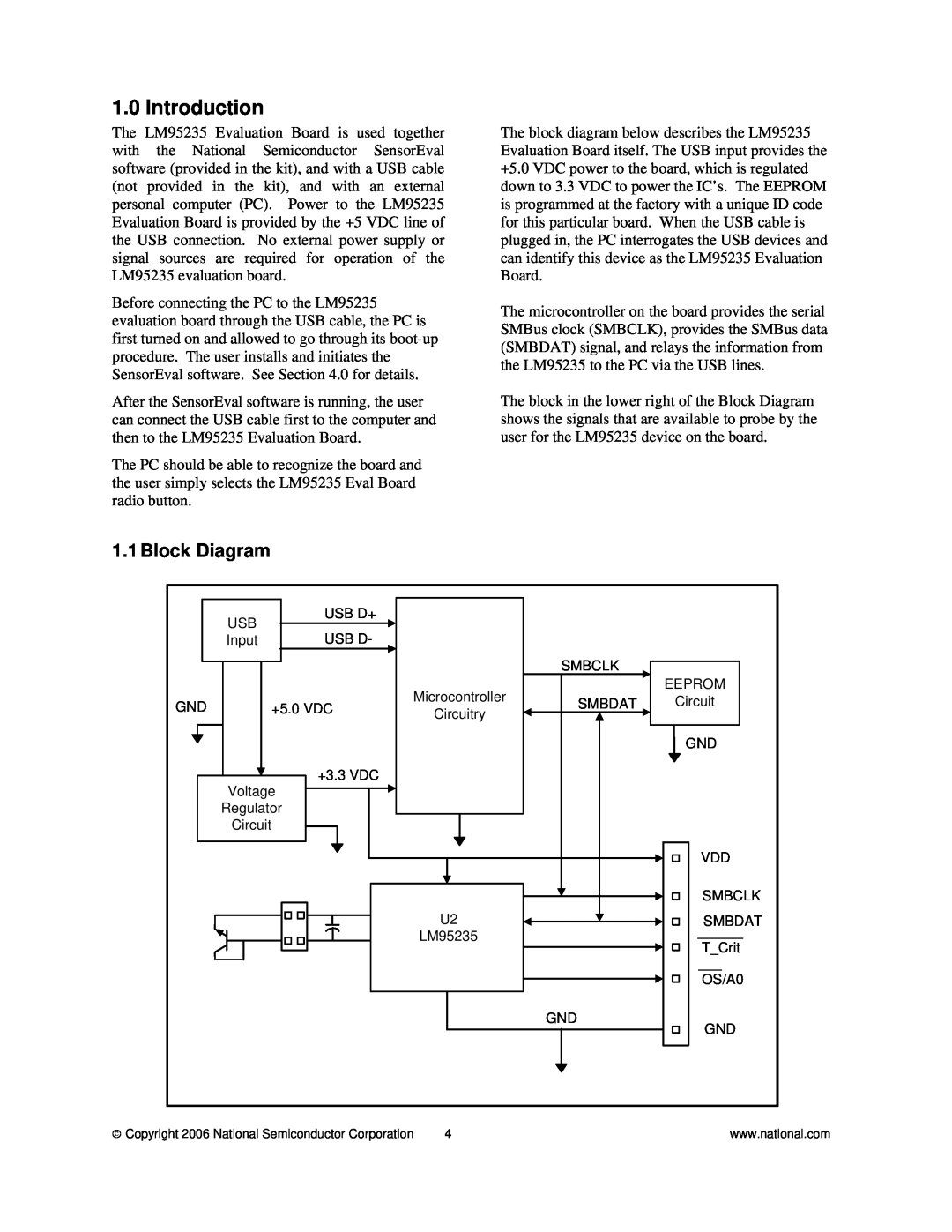
1.1Block Diagram
signals to any of the
Page 4
Image 4
Page 3
Page 5
Page 4
Image 4
Page 3
Page 5
Contents
LM95235 Evaluation Board User’s Guide
LM95235 Evaluation Board User’s Guide
Table of Contents
LM95235 Evaluation Board User’s Guide References
1.1Block Diagram
1.0 Introduction
2.0 Quick Start
6. The Screen should look like this
Copyright 2006 National Semiconductor Corporation
Important! NO EXTERNAL POWER SUPPLY OR SIGNAL INPUTS ARE REQUIRED
2.1 Quick Start Diagram
National Semiconductor
Connector Label
3.0 Functional Description
Description
Number
4.2 Operation
4.0 Software Installation and Operation
4.1 Installation
5.2 Electrical Schematic
5.0 Electrical and Mechanical Specifications
5.1 Electrical Specifications Power Requirements
NO EXTERNAL POWER SUPPLY INPUTS ARE REQUIRED
Figure 5.3 Layout diagram of the LM95235 Evaluation Board
5.3 Evaluation Board Layout
Note socket and socket area not stuffed
5.4 Bill of Materials for LM95235 Evaluation Board
Reference
Part
PCB Footprint
5.4 Mechanical Specifications
5.4.1 Operating Mechanical and Environmental Specifications
5.4.2 Evaluation Board Basic Dimensions
5.4.3 Electrostatic Discharge ESD Precautions
LIFE SUPPORT POLICY
BANNED SUBSTANCE COMPLIANCE
Top
Page
Image
Contents