BELT REPLACEMENT, Continued
1, Gently roll the pivot bracket off of the cutting unit. Now the belts can easily be removed from the reel pulleys.
2.Remove the top two bolts on the rear cutting unit (right side only) pivot bracket. (Noting this bracket is under spring pressure). Loosen the bottom bolt and use it as a pivot point. Roll back the pivot bracket allowing the spring pressure and belt tension to be released. (Use of a crescent wrench to get extra leverage is very helpful). Remove belt from rear cutting unit pulley.
3.To remove belts from the tractor you must remove the left front cover to access the main engine drive belts. Remove the front belt guide on the engine drive pulley, with clutch disengaged, the two main drive belts and the left wing cutting unit belt, can now be removed.
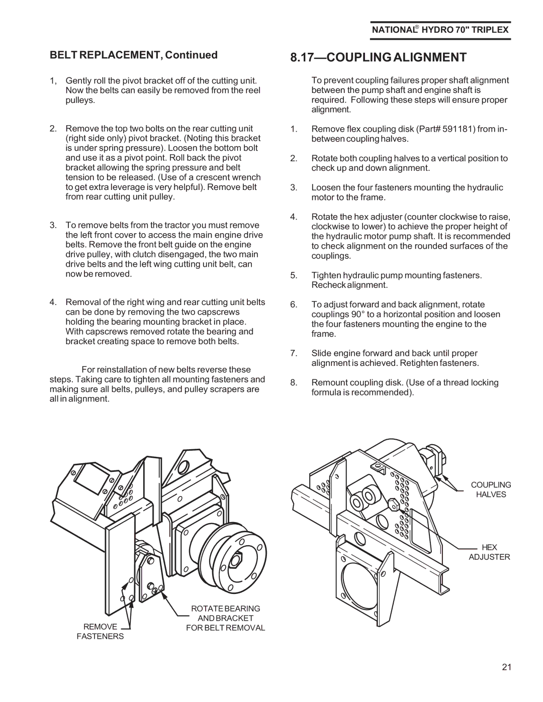
4.Removal of the right wing and rear cutting unit belts can be done by removing the two capscrews holding the bearing mounting bracket in place. With capscrews removed rotate the bearing and bracket creating space to remove both belts.
For reinstallation of new belts reverse these steps. Taking care to tighten all mounting fasteners and making sure all belts, pulleys, and pulley scrapers are all in alignment.
NATIONAL® HYDRO 70" TRIPLEX
8.17—COUPLING ALIGNMENT
To prevent coupling failures proper shaft alignment between the pump shaft and engine shaft is required. Following these steps will ensure proper alignment.
1.Remove flex coupling disk (Part# 591181) from in- between coupling halves.
2.Rotate both coupling halves to a vertical position to check up and down alignment.
3.Loosen the four fasteners mounting the hydraulic motor to the frame.
4.Rotate the hex adjuster (counter clockwise to raise, clockwise to lower) to achieve the proper height of the hydraulic motor pump shaft. It is recommended to check alignment on the rounded surfaces of the couplings.
5.Tighten hydraulic pump mounting fasteners. Recheck alignment.
6.To adjust forward and back alignment, rotate couplings 90° to a horizontal position and loosen the four fasteners mounting the engine to the frame.
7.Slide engine forward and back until proper alignment is achieved. Retighten fasteners.
8.Remount coupling disk. (Use of a thread locking formula is recommended).
COUPLING
HALVES
HEX
ADJUSTER
ROTATE BEARING
AND BRACKET
REMOVEFOR BELT REMOVAL
FASTENERS
21
