Model 120 Installation Procedure Manual
Liability Disclaimer
NEAX7400 ICS Model Installation Procedure Manual
100 101 102
107 108 109 110 111 Issue
Important Safety Considerations
Page
NEAX7400 ICS
NEAX7400 ICS
Table of Contents
Table of Contents
List of Illustrations
Title 003-24
AD-25182501LIST of Illustrations
List of Tables
Reference Manuals
During installation, refer also to the manuals below
Purpose
This manual covers the installation shown in Figure
HOW to Follow the Manual
Scope of Installation Works
Typical trunking diagram for the Pabx is shown in Figure
Trunking Diagram
Symbol Description
Description of Symbols in Trunking Diagram
1-PIM Configuration for Floor Standing Installation
System Configurations
2-PIM Configuration for Floor Standing Installation
8-PIM Configuration for Floor Standing Installation
1-PIM Configuration for Wall-Mounting Installation
PIM3 PIM2 PIM1 PIM0
Grounding Requirements
Precautions
Power, Ground Cabling and LIU for Australia
Static Electricity Guard
Static Electricity Guard
Circuitry
Procedure for Unplugging/Plugging Circuit Cards
Connecting Consoles’ Cables
Procedure Flowchart
Procedure
Contents Static Sensitive Handling Precautions Required
NAP Sheet 1/1 Unpacking
Unpacking Procedure
Marking and Drilling Floor Standing
NAP Sheet 1/2 Marking and Drilling
Confirmation of the Equipment Layout
Locate and mark the wall mounting points as shown in Figure
NAP Sheet 2/2 Marking and Drilling
Wall-Mounting
Installation of the Battm and Mdfm
NAP Sheet 1/29 Installation of Main Equipment
Installation of Modules
Connect the Rack Parts to the rear of the Base
NAP Sheet 2/29 Installation of Main Equipment
Floor Standing Installation
Connection of Rack Parts
NAP Sheet 3/29 Installation of Main Equipment
Connection of the PIM and the Rack Parts
NAP Sheet 4/29 Installation of Main Equipment
Connection of PIMs
NAP Sheet 5/29 Installation of Main Equipment
Wall-Mounting Installation
NAP Sheet 6/29 Installation of Main Equipment
Wall Type Recommended Fastener
NAP Sheet 7/29 Installation of Main Equipment
Recommended Fasteners
Mounting Pabx to Rack Parts
NAP Sheet 8/29 Installation of Main Equipment
Screwing the Rack Parts to a Wall
NAP Sheet 9/29 Installation of Main Equipment
10 Screwing the Rack Parts and the Base
NAP Sheet 10/29 Installation of Main Equipment
11 Modular Layout for 1 PIM Configuration
NAP Sheet 11/29 Installation of Main Equipment
13 Modular Layout for 3 PIM Configuration
NAP Sheet 12/29 Installation of Main Equipment
14 Modular Layout for 4 PIM Configuration
NAP Sheet 13/29 Installation of Main Equipment
Configuration
Installation of Main Equipment Sheet 14/29 NAP
Installation of Main Equipment Sheet 15/29 NAP
PIM Configuration
7PIM
Installation of Main Equipment Sheet 16/29 NAP
Layout for
Installation of Main Equipment Sheet 17/29 NAP
Stock Number
NAP Sheet 18/29 Installation of Main Equipment
19-Inch Rack-Mounting Installation
Precautions
19 1 PIM Configuration 19Rack Mount
NAP Sheet 19/29 Installation of Main Equipment
20 2 PIM Configuration 19Rack Mount
NAP Sheet 20/29 Installation of Main Equipment
21 3 PIM Configuration 19Rack Mount
NAP Sheet 21/29 Installation of Main Equipment
22 4 PIM Configuration 19Rack Mount
NAP Sheet 22/29 Installation of Main Equipment
23 Cable Connections and Switch Settings on PZ-PW86
NAP Sheet 23/29 Installation of Main Equipment
24 Cable Connections and Switch Settings on PZ-PW86A
NAP Sheet 24/29 Installation of Main Equipment
25 Cable Connection between the PZ-PW86 and the BWB
NAP Sheet 25/29 Installation of Main Equipment
26 AC CORD-A Wiring to Base
NAP Sheet 26/29 Installation of Main Equipment
27 Mounting of the BUS Cards
NAP Sheet 27/29 Installation of Main Equipment
28 BUS Cable
NAP Sheet 28/29 Installation of Main Equipment
29 Connection of the BUS Cables
NAP Sheet 29/29 Installation of Main Equipment
Installation of SN694 Attcon
NAP Sheet 1/9 Installation of Peripheral Equipment
ATT Cable Connection to SN694 Attcon
NAP Sheet 2/9 Installation of Peripheral Equipment
ATI CA-A
NAP Sheet 3/9 Installation of Peripheral Equipment
Connect the ATT cable to Main Equipment as shown in Figure
Installation Cable
NAP Sheet 4/9 Installation of Peripheral Equipment
Installation of SN611 Attcon
NAP Sheet 5/9 Installation of Peripheral Equipment
Jack Set Installation for SN611 Attcon
NAP Sheet 6/9 Installation of Peripheral Equipment
Access to Switch on SN611 Attcon
NAP Sheet 7/9 Installation of Peripheral Equipment
Switch Setting on SN611 Attcon
NAP Sheet 8/9 Installation of Peripheral Equipment
Cable Connection to SN611 Attcon
NAP Sheet 9/9 Installation of Peripheral Equipment
Internal Battery Connection
NAP Sheet 1/4 Connection of Battery
PWR CA-A
NAP Sheet 2/4 Connection of Battery
Internal Battery Connection for 8 PIMs Configuration
NAP Sheet 3/4 Connection of Battery
External Battery Connection
NAP Sheet 4/4 Connection of Battery
Cable Running to MDF
NAP Sheet 1/3 Cable Running to MDF
From Cable Number Designation Module Connection
NAP Sheet 2/3 Cable Running to MDF
MDF Cables for PIM
Example of Existing MDF Cable Running
NAP Sheet 3/3 Cable Running to MDF
Cable Connection to MDF
LTC Connector Card Slot Number Remarks
NAP Sheet 1/42 Termination of Cables on MDF
Location of LEN
NAP Sheet 2/42 Termination of Cables on MDF
LEN 0256 ~
NAP Sheet 3/42 Termination of Cables on MDF
NAP Sheet 4/42 Termination of Cables on MDF
Shows the LTC Connector Pin Arrangement PIM0 LTC0 ~ LTC2
PIM1 LTC0 ~ LTC2
NAP Sheet 5/42 Termination of Cables on MDF
PIM2 LTC0 ~ LTC2
NAP Sheet 6/42 Termination of Cables on MDF
PIM3 LTC0 ~ LTC2
NAP Sheet 7/42 Termination of Cables on MDF
PIM4 LTC0 ~ LTC2
NAP Sheet 8/42 Termination of Cables on MDF
PIM5 LTC0 ~ LTC2
NAP Sheet 9/42 Termination of Cables on MDF
PIM6 LTC0 ~ LTC2
NAP Sheet 10/42 Termination of Cables on MDF
PIM7 LTC0 ~ LTC2
NAP Sheet 11/42 Termination of Cables on MDF
TxT0 TxR0 RxT0 RxR0 TxT1 TxR1 RxT1 RxR1
NAP Sheet 12/42 Termination of Cables on MDF
MDF Cross Connections
TxT0 TxR0 RxT0 RxR0 TxT1 TxR1 RxT1 RxR1 50 MN 25 MJ
NAP Sheet 13/42 Termination of Cables on MDF
NAP Sheet 14/42 Termination of Cables on MDF
50 MN 25 MJ
NAP Sheet 15/42 Termination of Cables on MDF
O./D.I.D. Trunks Line C.O. Trunks PN-4COTE and PN-4DITB
NAP Sheet 16/42 Termination of Cables on MDF
Line C.O. Trunk PN-2COTD
NAP Sheet 17/42 Termination of Cables on MDF
Tie Line Trunk 4W E&M Trunk PN-2ODTA
NAP Sheet 18/42 Termination of Cables on MDF
NAP Sheet 19/42 Termination of Cables on MDF
LD Trunk PN-2LDTA
NAP Sheet 20/42 Termination of Cables on MDF
Line did Trunk PN-AUCA
NAP Sheet 21/42 Termination of Cables on MDF
Single Line Telephone SLT Standard Line PN-4LCE/4LCF
NAP Sheet 22/42 Termination of Cables on MDF
Long Line PN-AUCA
NAP Sheet 23/42 Termination of Cables on MDF
Dterm /DSS Console Standard Line PN-4DLCA
NAP Sheet 24/42 Termination of Cables on MDF
Long Line PN-2DLCB
NAP Sheet 25/42 Termination of Cables on MDF
SN611 Attcon and Dterm 6D/16D series telephones
NAP Sheet 26/42 Termination of Cables on MDF
NAP Sheet 27/42 Termination of Cables on MDF
Day/Night Mode Change by External Key
NAP Sheet 28/42 Termination of Cables on MDF
External TAS Indicator Outline of the Connections
NAP Sheet 29/42 Termination of Cables on MDF
16 MDF Cross Connection for a TAS Indicator with a Battery
NAP Sheet 30/42 Termination of Cables on MDF
18 Outline of the Paging Equipment Connection
NAP Sheet 31/42 Termination of Cables on MDF
MDF Cross Connection
NAP Sheet 32/42 Termination of Cables on MDF
NAP Sheet 33/42 Termination of Cables on MDF
20 Outline of the External Music Connection
NAP Sheet 34/42 Termination of Cables on MDF
21 MDF Cross Connection for External Music Equipment
NAP Sheet 35/42 Termination of Cables on MDF
NAP Sheet 36/42 Termination of Cables on MDF
NAP Sheet 37/42 Termination of Cables on MDF
22 Connecting Method of Music Source with D.C. Offset
23 MDF Cross Connection for External BGM Sources
NAP Sheet 38/42 Termination of Cables on MDF
24 Outline of the PFT Connection
NAP Sheet 39/42 Termination of Cables on MDF
25 MDF Cross Connection for the PFT
NAP Sheet 40/42 Termination of Cables on MDF
NAP Sheet 41/42 Termination of Cables on MDF
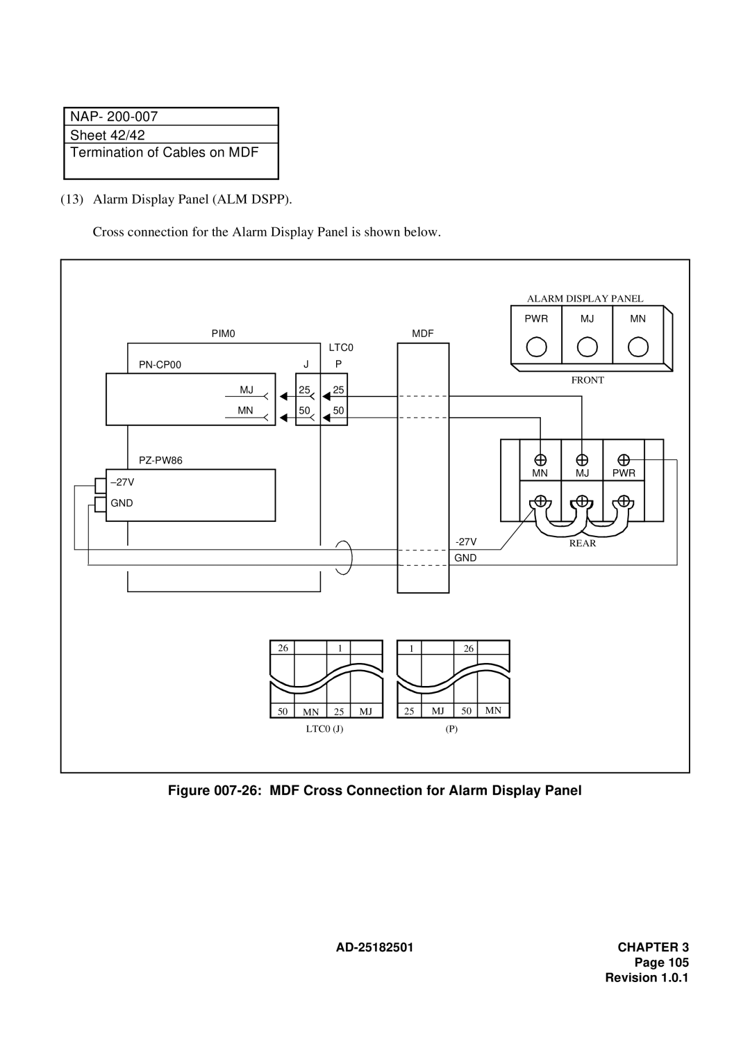
NAP Sheet 42/42 Termination of Cables on MDF
26 MDF Cross Connection for Alarm Display Panel
NAP Sheet 1/2 Mounting of Circuit Cards
Mounting Procedure
NAP Sheet 2/2 Mounting of Circuit Cards
Resident System Program
NAP Sheet 1/3 System Initialization and System Data Entry
System Initialization
All Clear, Except LEN0000 CAT
System Data Entry
CAT Customer Administration Terminal
NAP Sheet 2/3 System Initialization and System Data Entry
NAP Sheet 3/3 System Initialization and System Data Entry
MAT Maintainance Administration Terminal
Operation Test
NAP Sheet 1/1 Operation Test