NEC 1000 Series, 5800 Series, 1080Rf VLC Architecture, Dedicated Cache Coherency Interface CCI

Models: 5800 Series 1000 Series 1320Xf/1160Xf 1080Rf

1 12
Download 12 pages 39.83 Kb
Page 5
Image 5
VLC Architecture

VLC Architecture

High-speed / low latency Intra-Cell cache-to-cache data transfer

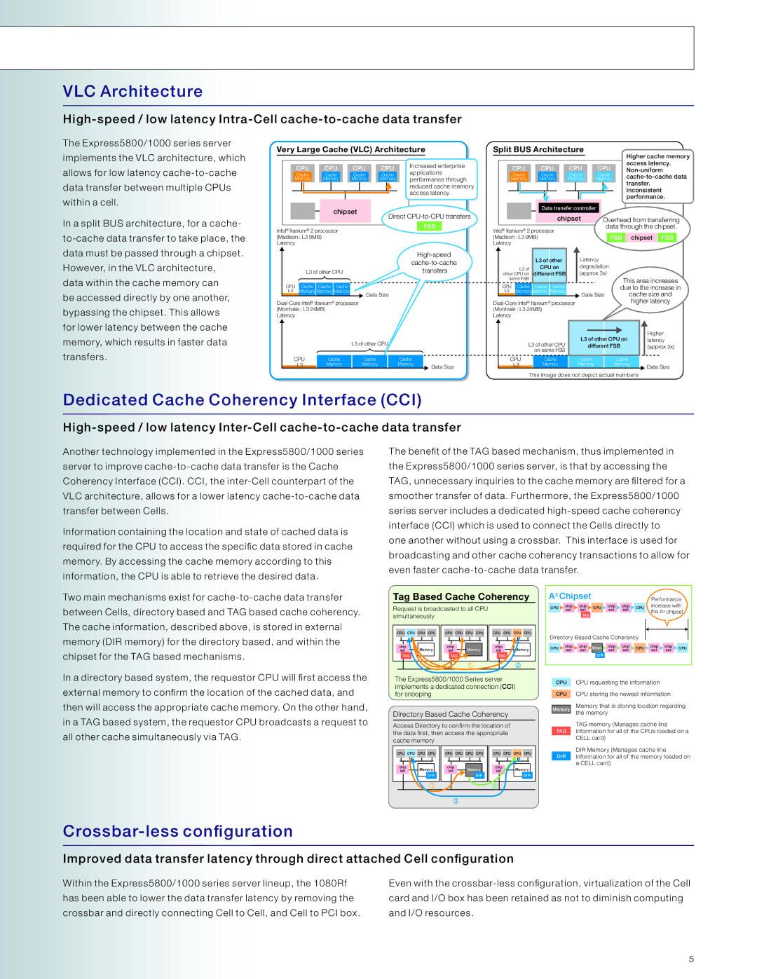
The Express5800/1000 series server implements the VLC architecture, which allows for low latency cache-to-cache data transfer between multiple CPUs within a cell.

In a split BUS architecture, for a cache- to-cache data transfer to take place, the data must be passed through a chipset. However, in the VLC architecture, data within the cache memory can

be accessed directly by one another, bypassing the chipset. This allows for lower latency between the cache memory, which results in faster data transfers.

Very Large Cache (VLC) Architecture


Increased enterprise


CPU


CPU


CPU


CPU


applications


Cache


Cache


Cache


Cache


Memory


Memory


Memory


Memory

performance through


reduced cache memory


access latency


Memory


chipset


Direct CPU-to-CPU transfers


FSB


Intel® Itanium® 2 processor


(Madison : L3 9MB)


Latency


High-speed


cache-to-cache


L3 of other CPU


transfers


CPU


Cache


Cache

Cache


L3


Memory

Memory

Memory


Data Size


Dual-Core Intel® Itanium® processor


(Montvale : L3 24MB)


Latency


L3 of other CPU


CPU


Cache


Cache

Cache


L3


Memory


Memory

Memory


Data Size


Split BUS Architecture


Higher cache memory


CPU


CPU


CPU


CPU


access latency.


Non-uniform


Cache


Cache


Cache


Cache


cache-to-cache data


Memory


Memory


Memory


Memory


transfer.


Inconsistent


performance.


Memory


Data transfer controller


chipset


Overhead

from transferring

Intel® Itanium® 2 processor


data

through the chipset.


(Madison : L3 9MB)


FSB

chipset

FSB


Latency


L3 of other

Latency


L3 of

CPU on

degradation


other CPU on

different FSB

(approx 3x)


same FSB


This area increases

CPU

Cache

Cache

Cache


due to the increase in

L3

Memory Memory Memory

Data Size

cache size and


Dual-Core Intel® Itanium® processor


higher latency

(Montvale : L3 24MB)


Latency


Higher


L3 of other CPU on

L3 of other CPU

latency


different FSB

(approx 3x)

on same FSB


CPU

Cache

Cache

Cache


L3

Memory

Memory

Memory

Data Size


This image does not depict actual numbers

Dedicated Cache Coherency Interface (CCI)

High-speed / low latency Inter-Cell cache-to-cache data transfer

Another technology implemented in the Express5800/1000 series server to improve cache-to-cache data transfer is the Cache Coherency Interface (CCI). CCI, the inter-Cell counterpart of the VLC architecture, allows for a lower latency cache-to-cache data transfer between Cells.

Information containing the location and state of cached data is required for the CPU to access the specific data stored in cache memory. By accessing the cache memory according to this information, the CPU is able to retrieve the desired data.

Two main mechanisms exist for cache-to-cache data transfer between Cells, directory based and TAG based cache coherency. The cache information, described above, is stored in external memory (DIR memory) for the directory based, and within the chipset for the TAG based mechanisms.

The benefit of the TAG based mechanism, thus implemented in the Express5800/1000 series server, is that by accessing the TAG, unnecessary inquiries to the cache memory are filtered for a smoother transfer of data. Furthermore, the Express5800/1000 series server includes a dedicated high-speed cache coherency interface (CCI) which is used to connect the Cells directly to one another without using a crossbar. This interface is used for broadcasting and other cache coherency transactions to allow for even faster cache-to-cache data transfer.

Tag Based Cache Coherency

A3 Chipset


Performance

Request is broadcasted to all CPU


CPU

chip

chip

CPU

chip

chip

CPU

increase with


set

set

set

set

the A3 chipset

simultaneously


TAG


CPU

CPU CPU CPU

CPU

CPU CPU CPU

CPU

CPU CPU CPU

Directory Based Cache Coherency


chip

Memory

chip

Memory

chip

Memory

CPU

chip

chip

Memory

chip

chip

CPU

chip

chip

CPU

set

set

set

set

set

set

set

set

set


TAG

TAG

TAG


DIR


In a directory based system, the requestor CPU will first access the external memory to confirm the location of the cached data, and then will access the appropriate cache memory. On the other hand, in a TAG based system, the requestor CPU broadcasts a request to all other cache simultaneously via TAG.

The Express5800/1000 Series server implements a dedicated connection (CCI) for snooping

Directory Based Cache Coherency

Access Directory to confirm the location of the data first, then access the appropriate cache memory

CPU

CPU

CPU

CPU

CPU

CPU

CPU

CPU

CPU

CPU

CPU

CPU

chip


Memory

chip


Memory

chip


Memory

set


set


set


DIR


DIR


DIR

CPU

CPU

Memory

TAG

DIR

CPU requesting the information

CPU storing the newest information

Memory that is storing location regarding the memory

TAG memory (Manages cache line information for all of the CPUs loaded on a CELL card)

DIR Memory (Manages cache line information for all of the memory loaded on a CELL card)

Crossbar-less configuration

Improved data transfer latency through direct attached Cell configuration

Within the Express5800/1000 series server lineup, the 1080Rf has been able to lower the data transfer latency by removing the crossbar and directly connecting Cell to Cell, and Cell to PCI box.

Even with the crossbar-less configuration, virtualization of the Cell card and I/O box has been retained as not to diminish computing and I/O resources.

5

Page 5
Image 5
NEC 1000 Series, 5800 Series, 1080Rf VLC Architecture, Dedicated Cache Coherency Interface CCI, Crossbar-less configuration