Replace Battery

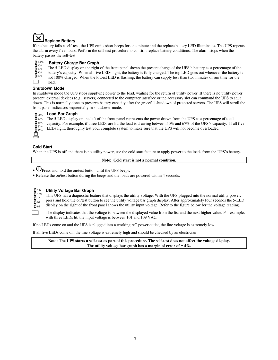
If the battery fails a self-test, the UPS emits short beeps for one minute and the replace battery LED illuminates. The UPS repeats the alarm every five hours. Perform the self-test procedure to confirm replace battery conditions. The alarm stops when the battery passes the self-test.

100%

80%

60%

40% 20%

Battery Charge Bar Graph

The 5-LED display on the right of the front panel shows the present charge of the UPS’s battery as a percentage of the battery’s capacity. When all five LEDs light, the battery is fully charged. The top LED goes out whenever the battery is not 100% charged. When the lowest LED is flashing, the battery can supply less than two minutes of run time for the load.

Shutdown Mode

In shutdown mode the UPS stops supplying power to the load, waiting for the return of utility power. If there is no utility power present, external devices (e.g., servers) connected to the computer interface or the accessory slot can command the UPS to shut down. This is normally done to preserve battery capacity after the graceful shutdown of protected servers. The UPS will scroll the front panel indicators sequentially in shutdown mode.

85%

67%

50% 33%

17%

Load Bar Graph

The 5-LED display on the left of the front panel represents the power drawn from the UPS as a percentage of total capacity. For example, if three LEDs are lit, the load is drawing between 50% and 67% of the UPS’s capacity. If all five LEDs light, thoroughly test your complete system to make sure that the UPS will not become overloaded.

Cold Start

When the UPS is off and there is no utility power, use the cold start feature to apply power to the loads from the UPS’s battery.

Note: Cold start is not a normal condition.

Press and hold the on/test button until the UPS beeps.

Release the on/test button during the beeps and the loads are powered within 4 seconds.

117

Utility Voltage Bar Graph

109

This UPS has a diagnostic feature that displays the utility voltage. With the UPS plugged into the normal utility power,

101

press and hold the on/test button to see the utility voltage bar graph display. After approximately four seconds the 5-LED

92

display on the right of the front panel shows the utility input voltage. Refer to the figure below for the voltage reading.

84

The display indicates that the voltage is between the displayed value from the list and the next higher value. For example, with three LEDs lit, the input voltage is between 101 and 109 VAC.

If no LEDs come on and the UPS is plugged into a working AC power outlet, the line voltage is extremely low.

If all five LEDs come on, the line voltage is extremely high and should be checked by an electrician

Note: The UPS starts a self-test as part of this procedure. The self-test does not affect the voltage display.

The utility voltage bar graph has a margin of error of ± 4%.

5

Page 8
Image 8
NEC N8580-31 user manual Replace Battery, Battery Charge Bar Graph, Shutdown Mode, Load Bar Graph, Cold Start

N8580-31 specifications

The NEC N8580-31 is a powerful and versatile telecommunications solution primarily designed for enterprise environments. This system stands out due to its robust architecture that supports diverse communication needs, making it an ideal choice for organizations looking to enhance their connectivity and operational efficiency.

One of the key features of the NEC N8580-31 is its high availability, ensuring continuous operation and minimal downtime. This is crucial for businesses that rely on uninterrupted communication to maintain productivity. The system is designed with redundancy in mind, incorporating backup power supplies and failover mechanisms to guarantee seamless service.

In terms of technology, the N8580-31 employs advanced VoIP (Voice over Internet Protocol) capabilities, enabling organizations to leverage their existing IP networks for voice communication. This feature not only reduces costs associated with traditional telephony but also enhances flexibility, allowing users to access communication tools from various devices and locations.

The NEC N8580-31 supports a wide range of telephony features, including call forwarding, voicemail, and conferencing. These features are complemented by sophisticated call management tools that enable organizations to monitor and analyze call traffic, ensuring efficient use of resources and improved customer service.

Another notable characteristic of the NEC N8580-31 is its scalability. As businesses grow, their communication needs often change. The N8580-31 can be easily expanded to accommodate additional users and features without significant upgrades or overhauls. This scalability is vital for businesses aiming to future-proof their investment in communication technologies.

The system also integrates seamlessly with various third-party applications and platforms, enhancing its functionality and enabling organizations to customize their communication solutions. This level of integration supports workflows and processes, allowing for improved collaboration among team members.

Moreover, the NEC N8580-31 prioritizes security, incorporating multiple layers of protection to safeguard sensitive communication and data. This is particularly important in today’s digital landscape, where data breaches and cyber threats are prevalent.

In summary, the NEC N8580-31 is a cutting-edge telecommunications solution that combines reliability, scalability, and advanced features. Its capabilities in VoIP, call management, and integration with other applications position it as a leading choice for enterprises seeking to enhance their communication systems while ensuring security and operational efficiency.