CM400 High Speed Cable Modem
You can use the LEDs to verify status and connections. The following table lists and describes each LED on the front panel of the cable modem.
Table 1. LED descriptions
| LED | Description | |
|
|
| |
| Power | • Green. Power is supplied to the cable modem. | |
|
|
| |
|
|
| • Off. No power is supplied to the cable modem. |
|
|
| |
| Downstream | • Solid green. One or more downstream channels are locked. | |
|
|
| |
|
|
| • Blinking green. The cable modem is scanning for a downstream channel. |
•Off. No downstream channel is locked.
Upstream | • Solid green. One or more upstream channels are locked. |
| |
| • Blinking green. The cable modem is scanning for an upstream channel. |
•Off. No upstream channel is locked.
Internet | • Solid green. The cable modem is online. | |
|
| • Blinking green. The cable modem is synchronizing with the cable provider’s cable |
|
| modem termination system (CMTS). |
|
| |
Ethernet
•Off. The cable modem is offline.
Note: The Internet LED is also referred to as the Online LED.
• Green. A device is connected to the Ethernet port and powered on.
• Off. No device is connected to the Ethernet port.
Back Panel
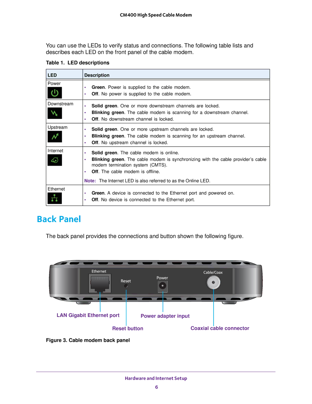
The back panel provides the connections and button shown the following figure.
|
|
|
|
|
|
|
|
|
|
|
|
|
|
|
|
|
|
|
|
|
|
|
|
|
|
|
|
|
|
LAN Gigabit Ethernet port |
|
|
|
|
|
| |||
| Power adapter input |
|
|
| |||||
|
|
| Reset |
| button | Coaxial |
|
| |
| cable connector | ||||||||
Figure 3. Cable modem back panel
Hardware and Internet Setup
6
