2nd0508.fm Page 1 Tuesday, May 8, 2001 10:18 AM
Introduction |
| Applications |
|
|
|
The NETGEAR® Model FS105 Fast Ethernet Switch provides you with a
Verify Package Contents
Product Illustration
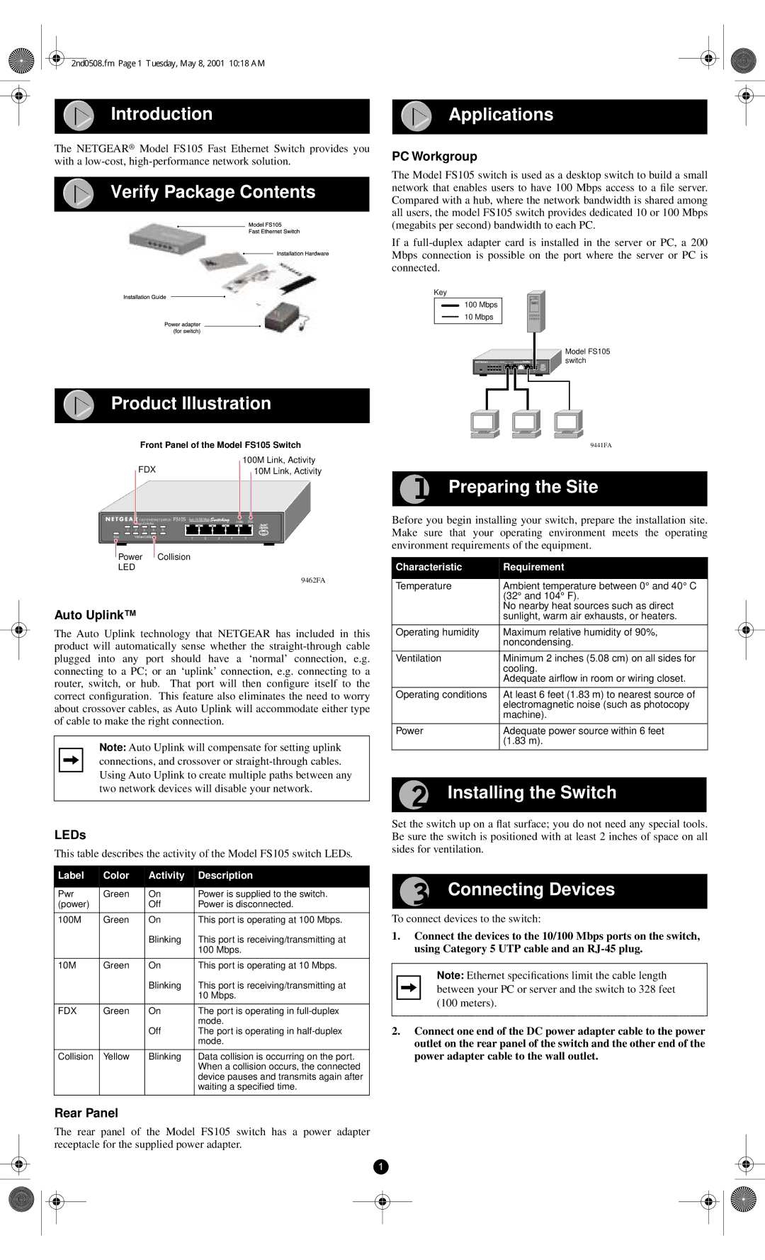
PC Workgroup
The Model FS105 switch is used as a desktop switch to build a small network that enables users to have 100 Mbps access to a file server. Compared with a hub, where the network bandwidth is shared among all users, the model FS105 switch provides dedicated 10 or 100 Mbps (megabits per second) bandwidth to each PC.
If a
Key
100Mbps
10Mbps
|
|
|
|
|
|
|
|
|
| Model FS105 |
|
|
|
| FS105100M |
| 10M |
|
| Blink=Act | switch |
|
|
|
|
|
| Auto 10/100 Mbps |
| On=Link |
| |
| Green = FDX |
|
|
|
|
|
|
| ||
1 | 2 | 3 | 4 | 5 |
|
|
|
|
|
|
Pwr | Yellow = Collision |
| 1 | 2 | 3 | 4 | 5 |
| ||
Front Panel of the Model FS105 Switch
100M Link, Activity
FDX | 10M Link, Activity |
|
| FAST ETHERNET SWITCH | FS105 | Auto 10/100 Mbps |
| 100M | FDX | |||
| Green=Link/Act |
|
|
|
|
|
|
| ||
1 | 2 | 3 | 4 | 5 |
|
|
|
|
|
|
Pow | Yellow=Collision |
|
| 1 | 2 | 3 | 4 | 5 | ||
![]() Power
Power ![]() Collision
Collision
LED
9462FA
Auto Uplink™
The Auto Uplink technology that NETGEAR has included in this product will automatically sense whether the
Note: Auto Uplink will compensate for setting uplink connections, and crossover or
LEDs
This table describes the activity of the Model FS105 switch LEDs.
Label | Color | Activity | Description |
|
|
|
|
Pwr | Green | On | Power is supplied to the switch. |
(power) |
| Off | Power is disconnected. |
|
|
|
|
100M | Green | On | This port is operating at 100 Mbps. |
|
| Blinking | This port is receiving/transmitting at |
|
|
| 100 Mbps. |
|
|
|
|
10M | Green | On | This port is operating at 10 Mbps. |
|
| Blinking | This port is receiving/transmitting at |
|
|
| 10 Mbps. |
|
|
|
|
FDX | Green | On | The port is operating in |
|
|
| mode. |
|
| Off | The port is operating in |
|
|
| mode. |
|
|
|
|
Collision | Yellow | Blinking | Data collision is occurring on the port. |
|
|
| When a collision occurs, the connected |
|
|
| device pauses and transmits again after |
|
|
| waiting a specified time. |
|
|
|
|
Rear Panel
The rear panel of the Model FS105 switch has a power adapter receptacle for the supplied power adapter.
1
9441FA
Preparing the Site
Before you begin installing your switch, prepare the installation site. Make sure that your operating environment meets the operating environment requirements of the equipment.
Characteristic | Requirement |
|
|
Temperature | Ambient temperature between 0° and 40° C |
| (32° and 104° F). |
| No nearby heat sources such as direct |
| sunlight, warm air exhausts, or heaters. |
|
|
Operating humidity | Maximum relative humidity of 90%, |
| noncondensing. |
|
|
Ventilation | Minimum 2 inches (5.08 cm) on all sides for |
| cooling. |
| Adequate airflow in room or wiring closet. |
|
|
Operating conditions | At least 6 feet (1.83 m) to nearest source of |
| electromagnetic noise (such as photocopy |
| machine). |
|
|
Power | Adequate power source within 6 feet |
| (1.83 m). |
|
|
Installing the Switch
Set the switch up on a flat surface; you do not need any special tools. Be sure the switch is positioned with at least 2 inches of space on all sides for ventilation.
Connecting Devices
To connect devices to the switch:
1.Connect the devices to the 10/100 Mbps ports on the switch, using Category 5 UTP cable and an
Note: Ethernet specifications limit the cable length between your PC or server and the switch to 328 feet (100 meters).
2.Connect one end of the DC power adapter cable to the power outlet on the rear panel of the switch and the other end of the power adapter cable to the wall outlet.