BROADBAND WITHOUT BOUNDARIES™
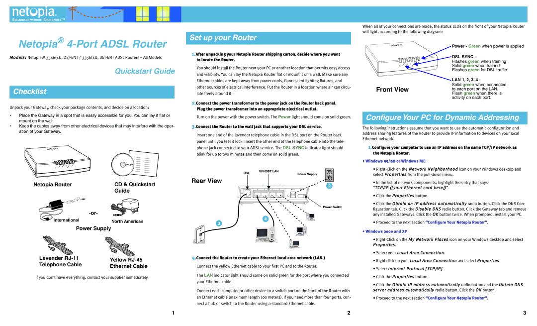
When all of your connections are made, the status LEDs on the front of your Netopia Router will light, according to the following diagram:
Netopia® 4-Port ADSL Router
Models: Netopia® 3346(EU,
Quickstart Guide
Checklist
Unpack your Gateway, check your package contents, and decide on a location:
Set up your Router
1.After unpacking your Netopia Router shipping carton, decide where you want to locate the Router.
You should install the Router near your PC or another location that permits easy access and visibility. You can lay the Netopia Router flat or mount it on a wall. Make sure any Ethernet cables are kept away from power cords, fluorescent lighting fixtures, and other sources of electrical interference. Put the Router in a location where air can circu- late freely around it.
2.Connect the power transformer to the power jack on the Router back panel. Plug the power transformer into an appropriate electrical outlet.
| 1 |
| 2 | LAN | 3 | LAN | 4 |
| SYNC | Power |
LAN |
| LAN |
|
|
|
| DSL |
|
| |
|
|
|
|
|
|
|
|
|
Front View
Power - Green when power is applied
DSL SYNC -
Flashes green when training Solid green when trained Flashes green for DSL traffic
LAN 1, 2, 3, 4 -
Solid green when connected to each port on the LAN. Flash green when there is activity on each port.
•Place the Gateway in a spot that is easily accessible for you.You can lay it flat or mount on the wall.
•Keep the cables away from other electrical devices that may interfere with the oper- ation of your Gateway.
| 1 |
|
|
| LAN | 4 |
|
| SYNC | Power |
|
| LAN | 2 | LAN | 3 |
|
|
|
|
|
LAN |
|
|
|
| DS | L |
|
|
Netopia Router | CD & Quickstart |
| Guide |
| |
International | North American |
Power Supply |
|
Lavender | Yellow | |
Telephone Cable | ||
Ethernet Cable | ||
|
If you don’t have everything, contact your supplier immediately.
1
Turn on the power with the power switch. The Power light should come on solid green.
3.Connect the Router to the wall jack that supports your DSL service.
Insert one end of the lavender telephone cable in the DSL port on the Router back panel until you feel it lock. Insert the other end of the telephone cable into the tele- phone jack connected to your ADSL service. The DSL SYNC indicator light should blink for up to two minutes and then come on solid green.
DSL | 10/100BT LAN | |
Power Supply | ||
|
Rear View
2
43 LAN 21Power Off / On
DSL
Power Switch
4
3
4.Connect the Router to create your Ethernet local area network (LAN.)
Connect the yellow Ethernet cable to your first PC and to the Router.
The LAN indicator light should come on solid green for the port where you connected your Ethernet cable.
Connect each computer or other device to a switch port on the back of the Router with an Ethernet cable (maximum length 100 meters). If you need more than four ports, con- nect a hub or switch to the Router using a standard Ethernet cable.
2
Configure Your PC for Dynamic Addressing
The following instructions assume that you want to use the automatic configuration and address sharing features of the Router to provide IP information to devices on your local Ethernet network.
1.Configure your computer to use an IP address on the same TCP/IP network as the Netopia Router.
•Windows 95/98 or Windows ME:
•
•In the list of network components, highlight the entry that says
“TCP//IIP ([[your Ethernet card here]])”.
•Click the Propertiies button.
•Click the Obtaiin an IIP address automatiicalllly radio button. Click the DNS Con- figuration tab. Click the Diisablle DNS radio button. Click the Gateway tab and remove any installed Gateways. Click the OK button twice. When prompted, restart your PC.
•Proceed to the next section “Configure Your Netopia Router”.
•Windows 2000 and XP
•
•Select your Locall Area Connectiion.
•Right click on your Locall Area Connectiion and select Propertiies.
•Select IInternet Protocoll [[TCP//IIP]].
•Click the Propertiies button.
•Click the Obtaiin IIP address automatiicalllly radio button and the Obtaiin DNS server address automatiicalllly radio button. Click the OK button.
•Proceed to the next section “Configure Your Netopia Router”.
3
