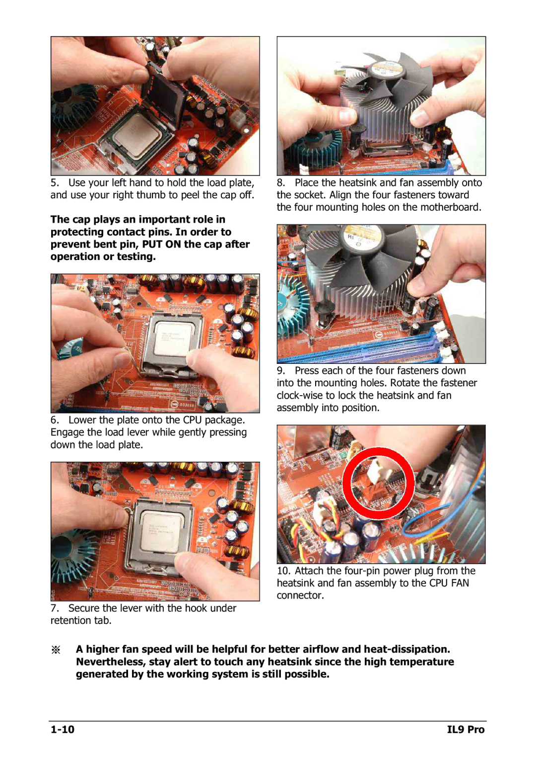
5.Use your left hand to hold the load plate, and use your right thumb to peel the cap off.
The cap plays an important role in protecting contact pins. In order to prevent bent pin, PUT ON the cap after operation or testing.
6.Lower the plate onto the CPU package. Engage the load lever while gently pressing down the load plate.
7.Secure the lever with the hook under retention tab.
8.Place the heatsink and fan assembly onto the socket. Align the four fasteners toward the four mounting holes on the motherboard.
9.Press each of the four fasteners down into the mounting holes. Rotate the fastener
10.Attach the
※A higher fan speed will be helpful for better airflow and
IL9 Pro |