Installation: New Construction |
(unfinished walls) |
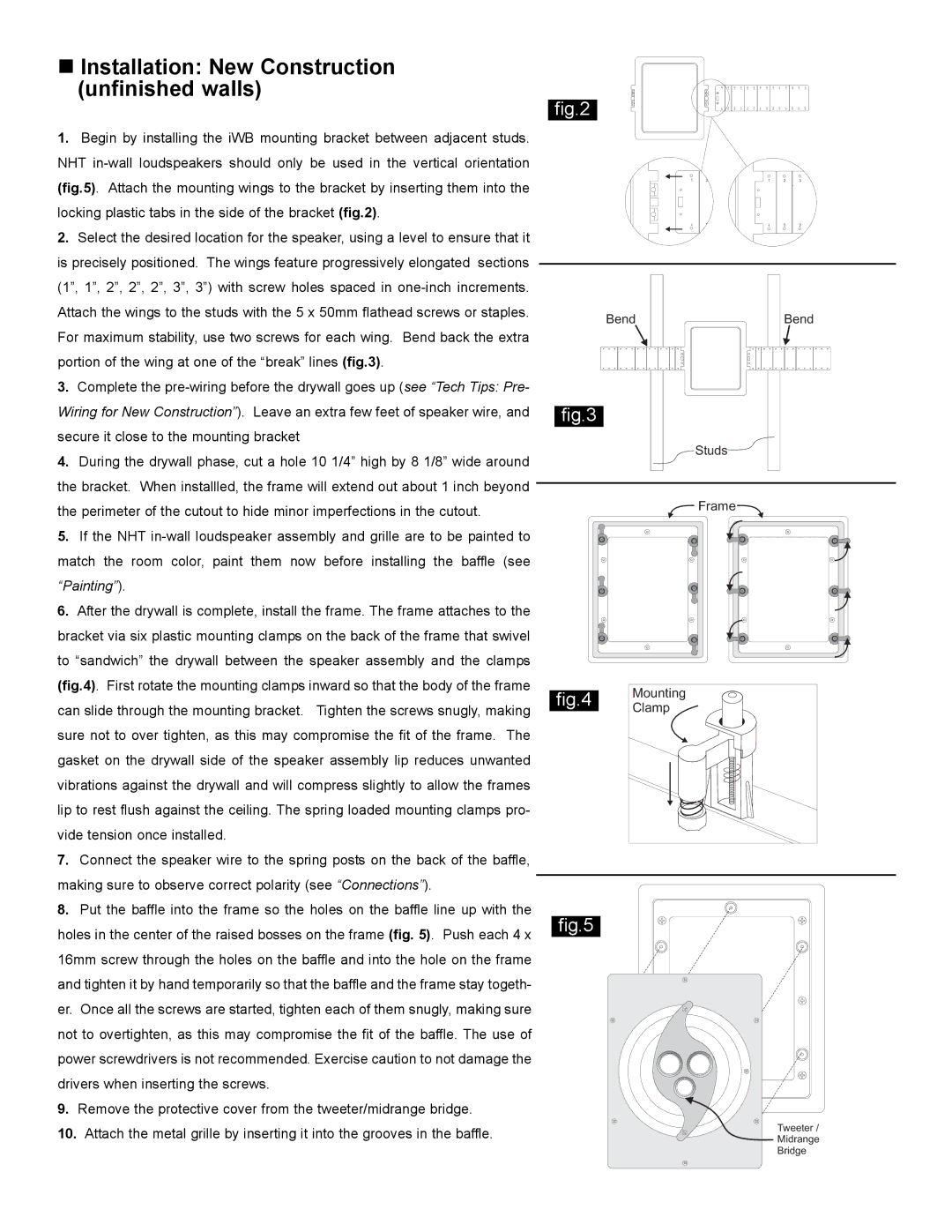
1. Begin by installing the iWB mounting bracket between adjacent studs. |
NHT |
(fig.5). Attach the mounting wings to the bracket by inserting them into the |
locking plastic tabs in the side of the bracket (fig.2). |
2. Select the desired location for the speaker, using a level to ensure that it |
is precisely positioned. The wings feature progressively elongated sections |
(1”, 1”, 2”, 2”, 2”, 3”, 3”) with screw holes spaced in |
Attach the wings to the studs with the 5 x 50mm flathead screws or staples. |
1 2 3 4 5 6 7 8 9 10 11 12 13 14
fig.2 | 1 | 2 | 3 | 4 | 5 | 6 | 7 | 8 | 9 | 10 | 11 | 12 | 13 | 14 |
1 | 2 | 1 | 2 | 3 | 4 |
1 | 2 | 1 | 2 | 3 | 4 |
For maximum stability, use two screws for each wing. Bend back the extra |
portion of the wing at one of the “break” lines (fig.3). |
3. Complete the |
Wiring for New Construction”). Leave an extra few feet of speaker wire, and |
secure it close to the mounting bracket |
4. During the drywall phase, cut a hole 10 1/4” high by 8 1/8” wide around |
the bracket. When installled, the frame will extend out about 1 inch beyond |
Bend
fig.3
Studs
Bend
the perimeter of the cutout to hide minor imperfections in the cutout. |
5. If the NHT |
match the room color, paint them now before installing the baffle (see |
“Painting”). |
6. After the drywall is complete, install the frame. The frame attaches to the |
bracket via six plastic mounting clamps on the back of the frame that swivel |
to “sandwich” the drywall between the speaker assembly and the clamps |
(fig.4). First rotate the mounting clamps inward so that the body of the frame |
can slide through the mounting bracket. Tighten the screws snugly, making |
sure not to over tighten, as this may compromise the fit of the frame. The |
gasket on the drywall side of the speaker assembly lip reduces unwanted |
vibrations against the drywall and will compress slightly to allow the frames |
lip to rest flush against the ceiling. The spring loaded mounting clamps pro- |
vide tension once installed. |
7. Connect the speaker wire to the spring posts on the back of the baffle, |
making sure to observe correct polarity (see “Connections”). |
8. Put the baffle into the frame so the holes on the baffle line up with the |
holes in the center of the raised bosses on the frame (fig. 5). Push each 4 x |
16mm screw through the holes on the baffle and into the hole on the frame |
and tighten it by hand temporarily so that the baffle and the frame stay togeth- |
er. Once all the screws are started, tighten each of them snugly, making sure |
not to overtighten, as this may compromise the fit of the baffle. The use of |
power screwdrivers is not recommended. Exercise caution to not damage the |
drivers when inserting the screws. |
9. Remove the protective cover from the tweeter/midrange bridge. |
10. Attach the metal grille by inserting it into the grooves in the baffle. |
![]() Frame
Frame ![]()
fig.4 Mounting Clamp
fig.5
Tweeter /
Midrange
Bridge