6.Level Control for Channels 1&2
These two controls are used to adjust output level of channel 1 and channel 2 respectively.
7.UP/DOWN Key
This key is used to move inside the menus or to modify the parameter's value.
8.SELECT Key
This key is used to select the menu that you wish to edit.
9.ENTER Key
This key is used to edit or confirm the parameter's value.
10.Fan
The fan can accelerate the flow of air to lower the temperature inside unit.The inside temperature deter- mines the fan speed which controls the inside air flowing speed.
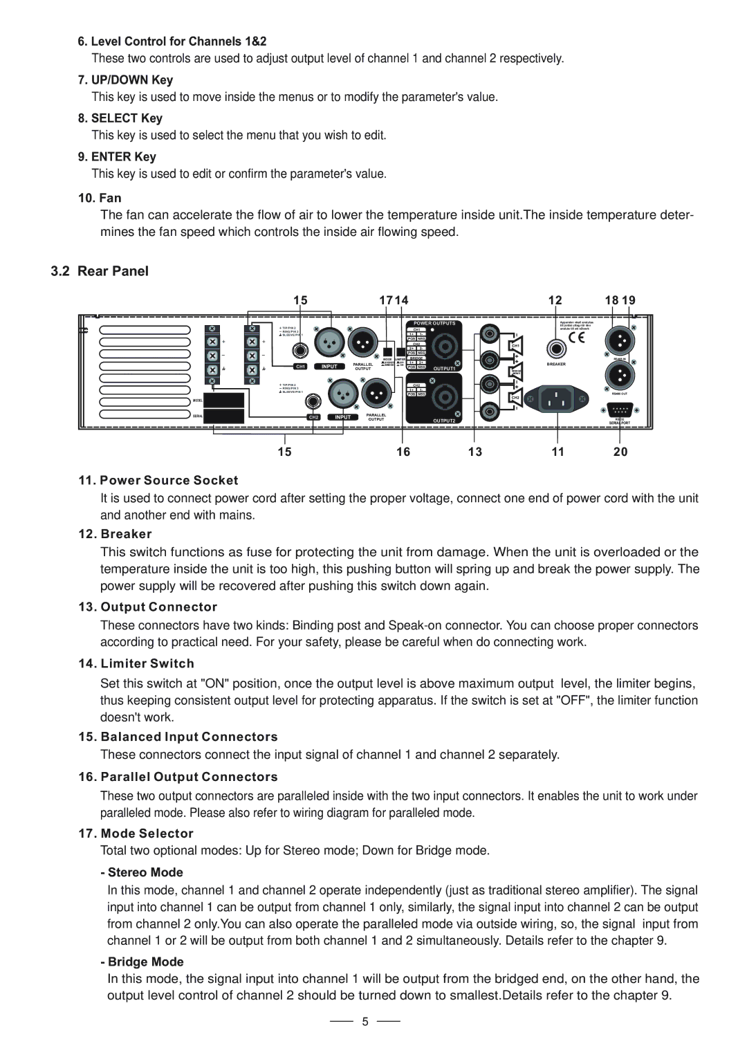
3.2 Rear Panel
MODEL
SERIAL
15 |
|
| 1714 |
|
| 12 | 18 19 | ||
|
|
|
|
| POWER OUTPUTS | Apparaten skall anslutas |
| ||
|
|
|
|
| till jordat uttag nar den |
| |||
TIP/PIN 2 |
|
|
|
| CH1 |
| ansluts till ett natverk |
| |
RING/PIN 3 |
|
|
|
|
|
|
| ||
SLEEVE/PIN 1 |
|
|
|
| 1+ | 1- |
|
|
|
2 | 1 |
|
|
| POS | NEG |
|
|
|
| 3 |
|
|
| CH2 |
| CH1 |
| |
|
|
|
|
|
|
| |||
|
|
|
|
| 2+ | 2- |
|
| |
|
|
|
|
|
|
|
| ||
|
|
|
|
| POS | NEG |
|
|
|
|
|
| MODE | LIMITER | BRIDGE |
|
| RS485 IN | |
|
| PARALLEL | STEREO | OFF | 1+ | 2+ |
| BREAKER |
|
CH1 |
| BRIDGE | ON | POS | NEG |
|
| ||
| OUTPUT |
|
| OUTPUT1 |
|
| |||
|
|
|
|
|
| BRIDGE |
| ||
|
|
|
|
|
|
|
| MONO |
|
TIP/PIN 2 |
|
|
|
| CH2 |
|
|
| |
RING/PIN 3 | 2 |
|
|
| 1+ | 1- |
|
|
|
SLEEVE/PIN 1 | 1 |
|
|
|
|
| |||
|
|
| POS | NEG |
|
| RS485 OUT | ||
|
| 3 |
|
|
|
| |||
|
|
|
|
|
|
|
| CH2 |
|
CH2 |
| PARALLEL |
|
|
|
|
|
| |
| OUTPUT |
|
|
| OUTPUT2 |
| RS232 | ||
|
|
|
|
|
| ||||
|
|
|
|
|
|
|
| SERIAL PORT | |
|
|
|
|
|
|
|
|
| |
15 | 16 | 13 | 11 | 20 |
11.Power Source Socket
It is used to connect power cord after setting the proper voltage, connect one end of power cord with the unit and another end with mains.
12.Breaker
This switch functions as fuse for protecting the unit from damage. When the unit is overloaded or the temperature inside the unit is too high, this pushing button will spring up and break the power supply. The power supply will be recovered after pushing this switch down again.
13.Output Connector
These connectors have two kinds: Binding post and
14.Limiter Switch
Set this switch at "ON" position, once the output level is above maximum output level, the limiter begins, thus keeping consistent output level for protecting apparatus. If the switch is set at "OFF", the limiter function doesn't work.
15.Balanced Input Connectors
These connectors connect the input signal of channel 1 and channel 2 separately.
16.Parallel Output Connectors
These two output connectors are paralleled inside with the two input connectors. It enables the unit to work under paralleled mode. Please also refer to wiring diagram for paralleled mode.
17.Mode Selector
Total two optional modes: Up for Stereo mode; Down for Bridge mode.
-Stereo Mode
In this mode, channel 1 and channel 2 operate independently (just as traditional stereo amplifier). The signal input into channel 1 can be output from channel 1 only, similarly, the signal input into channel 2 can be output from channel 2 only.You can also operate the paralleled mode via outside wiring, so, the signal input from channel 1 or 2 will be output from both channel 1 and 2 simultaneously. Details refer to the chapter 9.
-Bridge Mode
In this mode, the signal input into channel 1 will be output from the bridged end, on the other hand, the output level control of channel 2 should be turned down to smallest.Details refer to the chapter 9.
5