Replacement Parts
You may purchase replacement parts through your local RV dealer or authorized Norcold Service Center.
Wiring Diagram and Pictorial
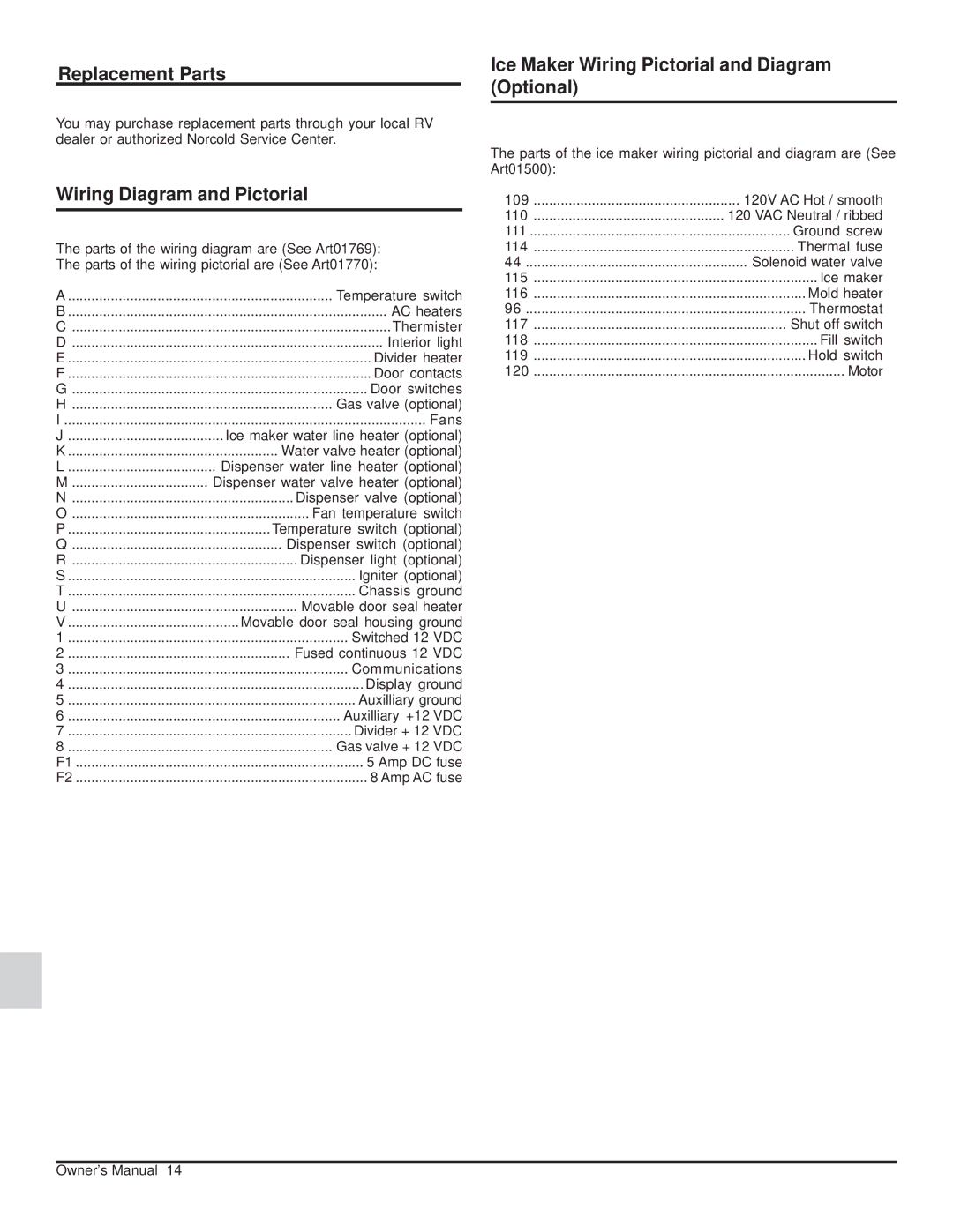
The parts of the wiring diagram are (See Art01769): The parts of the wiring pictorial are (See Art01770):
A | Temperature switch |
B | AC heaters |
C | Thermister |
D | Interior light |
E | Divider heater |
F | Door contacts |
G | Door switches |
H | Gas valve (optional) |
I | Fans |
J | Ice maker water line heater (optional) |
K | Water valve heater (optional) |
L | Dispenser water line heater (optional) |
M | Dispenser water valve heater (optional) |
N | Dispenser valve (optional) |
O | Fan temperature switch |
P | Temperature switch (optional) |
Q | Dispenser switch (optional) |
R | Dispenser light (optional) |
S | Igniter (optional) |
T | Chassis ground |
U | Movable door seal heater |
V | Movable door seal housing ground |
1 | Switched 12 VDC |
2 | Fused continuous 12 VDC |
3 | Communications |
4 | Display ground |
5 | Auxilliary ground |
6 | Auxilliary +12 VDC |
7 | Divider + 12 VDC |
8 | Gas valve + 12 VDC |
F1 | 5 Amp DC fuse |
F2 | 8 Amp AC fuse |
Ice Maker Wiring Pictorial and Diagram (Optional)
The parts of the ice maker wiring pictorial and diagram are (See Art01500):
109 | ..................................................... 120V AC Hot / smooth |
110 | ................................................. 120 VAC Neutral / ribbed |
111 | ................................................................... Ground screw |
114 | ................................................................... Thermal fuse |
44 | Solenoid water valve |
115 | ......................................................................... Ice maker |
116 | ...................................................................... Mold heater |
96 | Thermostat |
117 | ................................................................. Shut off switch |
118 | ......................................................................... Fill switch |
119 | ...................................................................... Hold switch |
120 | ................................................................................ Motor |
Owner’s Manual 14
