Headset Reference Design v1.0
3.2.1.1Headset interface
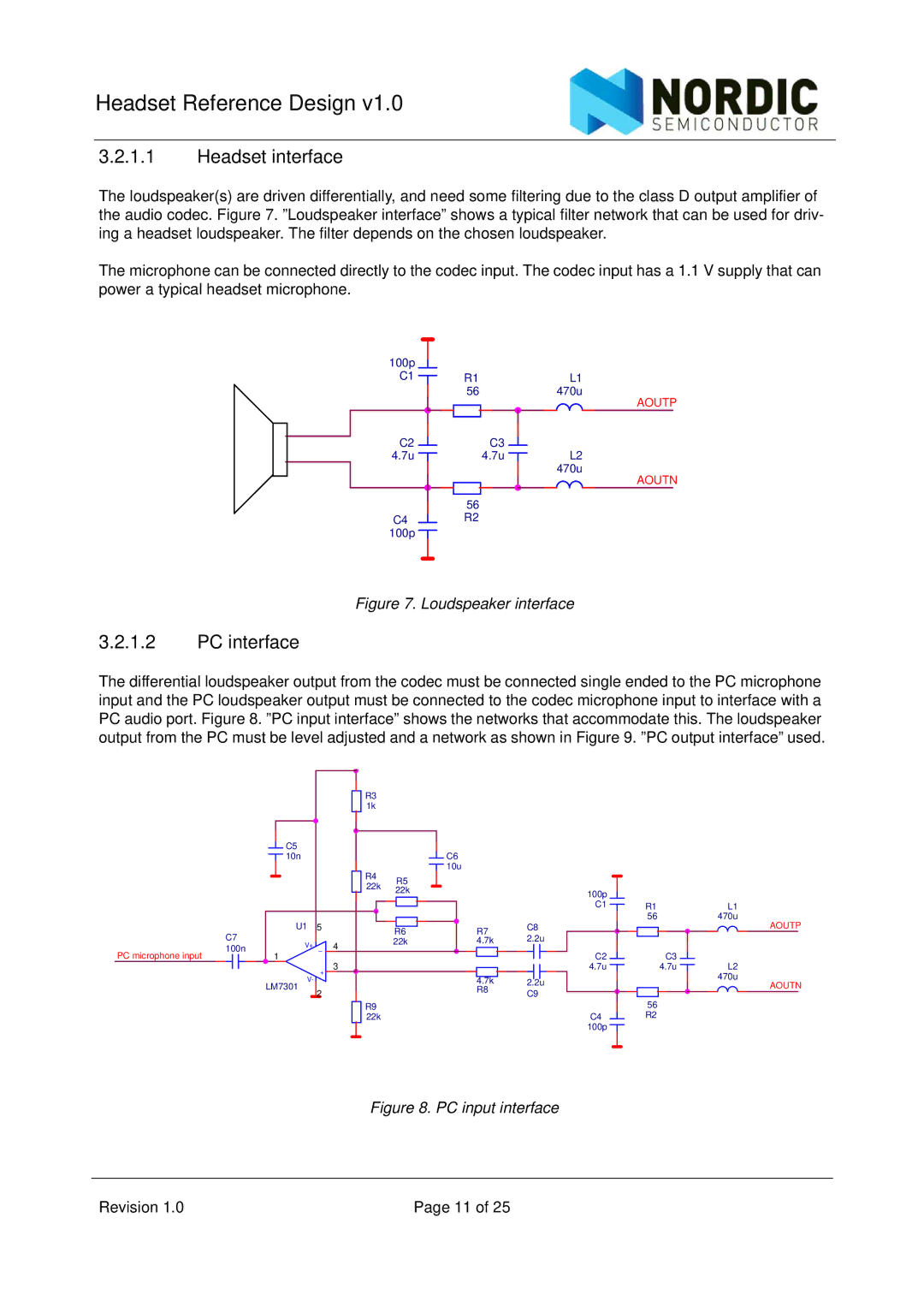
The loudspeaker(s) are driven differentially, and need some filtering due to the class D output amplifier of the audio codec. Figure 7. ”Loudspeaker interface” shows a typical filter network that can be used for driv- ing a headset loudspeaker. The filter depends on the chosen loudspeaker.
The microphone can be connected directly to the codec input. The codec input has a 1.1 V supply that can power a typical headset microphone.
100p |
|
|
C1 | R1 | L1 |
| 56 | 470u |
|
| AOUTP |
C2 | C3 |
|
4.7u | 4.7u | L2 |
|
| 470u |
|
| AOUTN |
| 56 |
|
C4 | R2 |
|
100p |
|
|
Figure 7. Loudspeaker interface
3.2.1.2PC interface
The differential loudspeaker output from the codec must be connected single ended to the PC microphone input and the PC loudspeaker output must be connected to the codec microphone input to interface with a PC audio port. Figure 8. ”PC input interface” shows the networks that accommodate this. The loudspeaker output from the PC must be level adjusted and a network as shown in Figure 9. ”PC output interface” used.
![]() C5
C5 ![]() 10n
10n
R3
1k
R4 R5
![]() C6
C6 ![]() 10u
10u
PC microphone input
C7
100n
U1 5
1V+ - 4
22k 22k
|
|
|
|
|
|
|
|
|
| C8 | ||
|
|
|
|
|
|
|
|
|
| |||
R6 |
|
| R7 |
|
|
| ||||||
22k |
|
| 4.7k |
|
|
| 2.2u | |||||
|
|
|
|
|
|
|
|
|
|
|
|
|
|
|
|
|
|
|
|
|
|
|
|
|
|
100p |
|
|
C1 | R1 | L1 |
| 56 | 470u |
|
| AOUTP |
C2 |
| C3 |
+
V-
3
4.7k | 2.2u |
4.7u |
|
| 4.7u |
|
| L2 |
|
|
|
| |||
|
|
|
|
|
| 470u |
LM7301
2
R8 | C9 |
|
R9
22k
| AOUTN |
| 56 |
C4 | R2 |
100p |
|
Figure 8. PC input interface
Revision 1.0 | Page 11 of 25 |