13
GRAM
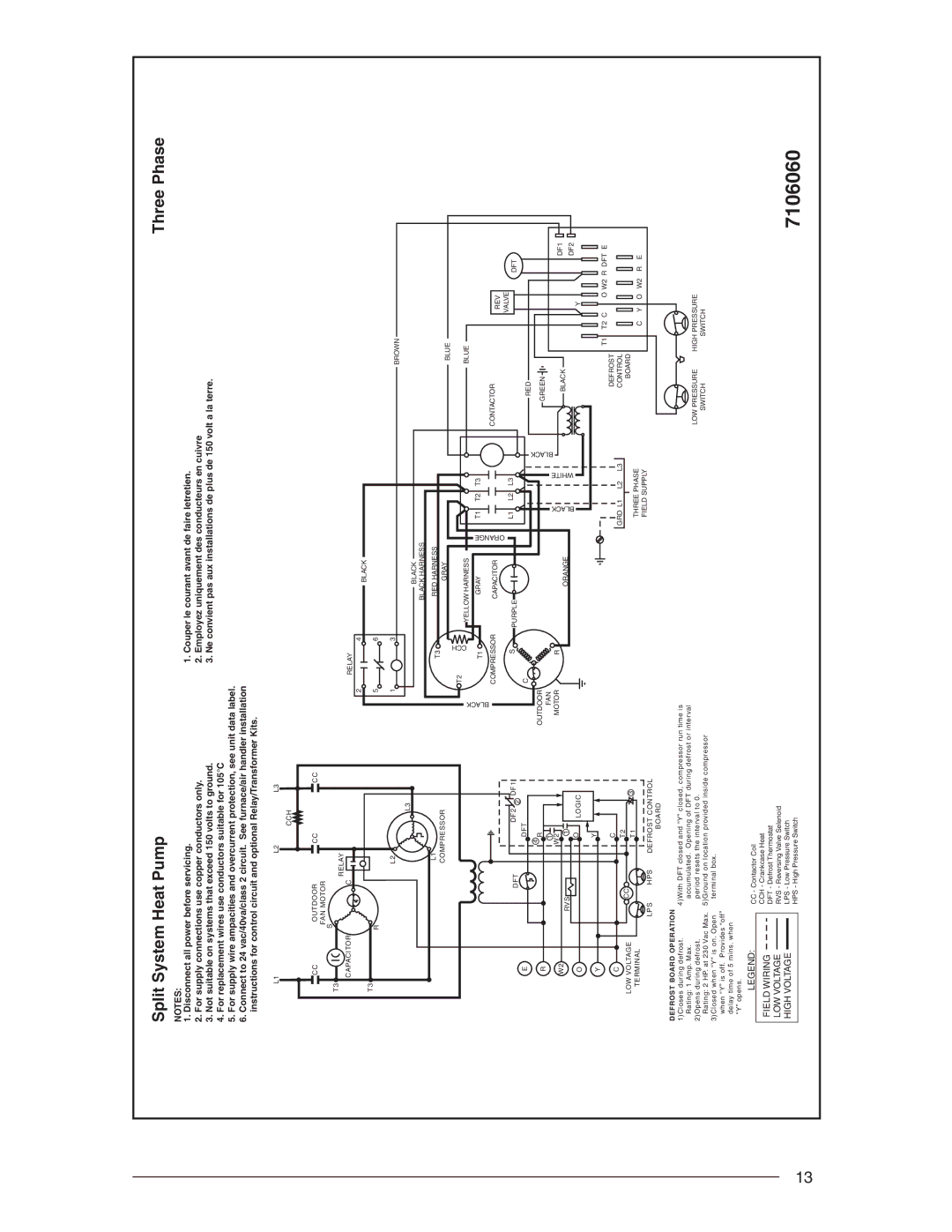
Split System Heat Pump | Three Phase |
NOTES: |
|
1. Disconnect all power before servicing. | 1. Couper le courant avant de faire letretien. |
2. For supply connections use copper conductors only. | 2. Employez uniquement des conducteurs en cuivre |
3. Not suitable on systems that exceed 150 volts to ground. | 3. Ne convient pas aux installations de plus de 150 volt a la terre. |
4.For replacement wires use conductors suitable for 105°C
5.For supply wire ampacities and overcurrent protection, see unit data label.
6.Connect to 24 vac/40va/class 2 circuit. See furnace/air handler installation instructions for control circuit and optional Relay/Transformer Kits.
L1 |
|
| L2 |
| L3 |
|
|
|
|
|
|
|
|
|
|
|
|
|
|
|
|
|
| CCH |
|
|
|
|
|
|
|
|
|
|
|
|
|
|
|
CC | OUTDOOR | CC |
| CC |
|
|
|
|
|
|
|
|
|
|
|
|
|
| |
| FAN MOTOR |
|
|
|
|
|
|
|
|
|
|
|
|
|
|
|
|
| |
T3 | S |
|
|
|
|
|
|
|
|
|
|
|
|
|
|
|
|
|
|
| RELAY |
|
|
|
|
|
|
|
|
|
|
|
|
|
|
|
| ||
CAPACITOR |
|
|
|
|
|
|
|
|
|
|
|
|
|
|
|
|
| ||
| C |
|
|
|
| RELAY |
|
|
|
|
|
|
|
|
|
|
|
| |
|
|
|
|
| 2 |
| 4 | BLACK |
|
|
|
|
|
|
|
|
|
|
|
T3 |
|
|
|
|
|
|
|
|
|
|
|
|
|
|
|
|
|
| |
R |
|
|
| 5 |
| 6 |
|
|
|
|
|
|
|
|
|
|
|
| |
|
|
|
|
|
|
|
|
|
|
|
|
|
|
|
|
| |||
|
|
| L2 |
| 1 |
| 3 |
|
|
|
|
|
|
| BROWN |
|
|
|
|
|
|
|
|
|
|
|
|
|
|
|
|
|
|
|
|
|
|
| |
|
|
|
| L3 |
|
|
| BLACK |
|
|
|
|
|
|
|
|
|
|
|
|
|
|
|
|
|
|
|
|
|
|
|
|
|
|
|
|
|
| |
|
|
|
|
|
|
|
| BLACK HARNESS |
|
|
|
|
|
|
|
|
|
|
|
|
|
| L1 |
|
|
| T3 | RED HARNESS |
|
|
|
|
|
|
|
|
|
|
|
|
|
| COMPRESSOR |
|
| GRAY |
|
|
|
|
|
|
|
|
|
|
| ||
|
|
|
|
|
|
|
|
|
|
|
| BLUE |
|
|
|
| |||
|
|
|
|
|
|
| CCH |
|
|
|
|
|
|
|
|
|
|
| |
|
|
|
|
|
| T2 | YELLOW HARNESS |
|
|
|
|
|
| BLUE |
|
|
|
| |
|
|
|
|
|
|
|
|
|
|
|
|
|
|
|
|
| |||
|
|
|
|
| BLACK |
|
| ORANGE |
|
|
|
|
|
|
|
|
| ||
|
|
|
|
|
| T1 | GRAY | T1 | T2 | T3 |
|
|
|
|
|
|
| ||
|
|
|
|
|
|
|
|
|
|
|
|
|
|
|
|
|
|
| |
|
|
|
|
|
| COMPRESSOR | CAPACITOR |
|
|
|
|
|
| CONTACTOR |
| REV |
| ||
|
|
|
|
|
|
|
|
|
|
|
|
|
|
|
|
|
| ||
|
|
|
| DF2 2 DF1 |
| S |
|
| L1 | L2 | L3 |
|
|
| VALVE | DFT | |||
|
| DFT |
|
| PURPLE |
|
|
|
|
|
|
| |||||||
|
|
|
|
|
|
|
|
|
|
|
|
|
|
| |||||
E |
|
| DFT |
| C |
|
|
|
|
|
|
| BLACK | RED |
|
|
|
| |
|
|
|
|
|
|
|
|
|
| BLACK |
|
| WHITE |
|
|
|
| ||
| RVS |
| 1 |
| OUTDOOR |
|
| ORANGE |
|
|
|
|
|
|
| DF2 | |||
R |
|
| 4 R |
|
|
|
|
|
|
|
|
|
| GREEN |
|
|
|
| |
|
|
| 1 |
| FAN |
|
|
|
|
|
|
|
|
|
|
|
|
|
|
W2 |
|
| W2 |
| MOTOR |
| R |
|
|
|
|
|
|
| BLACK |
|
|
| DF1 |
|
|
|
|
|
|
|
|
|
|
|
|
|
|
|
|
| |||
O |
|
| O | LOGIC |
|
|
|
|
|
|
|
|
|
|
|
|
| Y |
|
Y |
|
| Y |
|
|
|
|
|
|
|
|
|
|
|
|
|
|
|
|
|
|
|
|
|
|
|
|
|
|
|
|
|
| T1 | T2 C |
| O W2 R DFT E | ||
|
|
|
|
|
|
|
|
|
|
|
|
|
|
|
| ||||
C |
|
| C |
|
|
|
|
|
| GRD L1 | L2 | L3 |
| DEFROST |
|
|
|
| |
|
| T2 |
|
|
|
|
|
|
| CONTROL |
|
|
|
| |||||
| CC |
|
|
|
|
|
|
|
|
|
|
|
| ||||||
LOW VOLTAGE |
|
|
|
|
|
|
|
|
|
|
|
| BOARD |
|
|
|
| ||
| T1 |
| 3 |
|
|
|
|
|
|
|
|
|
|
|
|
| |||
|
|
|
|
|
|
| THREE PHASE |
|
|
|
|
| |||||||
TERMINAL |
|
|
|
|
|
|
|
|
|
| C | Y | O W2 | R E | |||||
|
|
|
|
|
|
|
|
|
|
| |||||||||
|
|
|
|
|
|
|
|
|
| FIELD SUPPLY |
|
| |||||||
| LPS | HPS | DEFROST CONTROL |
|
|
|
|
|
|
|
|
|
| ||||||
|
|
|
|
|
|
|
|
|
|
|
|
|
|
| |||||
|
|
|
| BOARD |
|
|
|
|
|
|
|
|
|
|
|
|
|
|
|
DEFROST BOARD OPERATION | 4)With DFT closed and “Y” closed, compressor run time is |
|
|
|
|
|
|
|
|
|
|
| ||||
1)Closes during defrost. |
|
|
|
|
|
|
|
|
|
|
| |||||
Rating: 1 Amp. Max. | accumulated. Opening of DFT during defrost or interval | LOW PRESSURE | HIGH PRESSURE | |||||||||||||
2)Opens during defrost. | period resets the interval to 0. | |||||||||||||||
| SWITCH | SWITCH | ||||||||||||||
Rating: 2 HP. at 230 Vac Max. 5)Ground on location provided inside compressor |
| |||||||||||||||
|
|
|
|
|
|
|
|
|
|
| ||||||
3)Closed when “Y” is on. Open | terminal box. |
|
|
|
|
|
|
|
|
|
|
| ||||
when “Y” is off. Provides “off” |
|
|
|
|
|
|
|
|
|
|
|
| ||||
delay time of 5 mins. when |
|
|
|
|
|
|
|
|
|
|
|
| ||||
“Y” opens. |
|
|
|
|
|
|
|
|
|
|
|
| ||||
LEGEND: |
| CC - Contactor Coil |
|
|
|
|
|
|
|
|
|
|
| |||
FIELD WIRING |
| CCH - Crankcase Heat |
|
|
|
|
|
|
|
|
|
|
| |||
| DFT - Defrost Thermostat |
|
|
|
|
|
|
|
|
|
|
| ||||
LOW VOLTAGE |
|
|
| RVS - Reversing Valve Selenoid |
|
|
|
|
|
| 7106060 | |||||
|
|
|
|
|
|
|
| |||||||||
HIGH VOLTAGE |
|
|
| LPS - Low Pressure Switch |
|
|
|
|
|
| ||||||
|
|
|
|
|
|
|
| |||||||||
|
|
|
| HPS - High Pressure Switch |
|
|
|
|
|
| ||||||
|
|
|
|
|
|
|
|
|
|
|
|
|
|
|
| |