1 | 2 |
|
|
|
|
| Uplink/Expansion Module | 25 | 26 | 27 | 28 |
100
10
F Dx
Activity
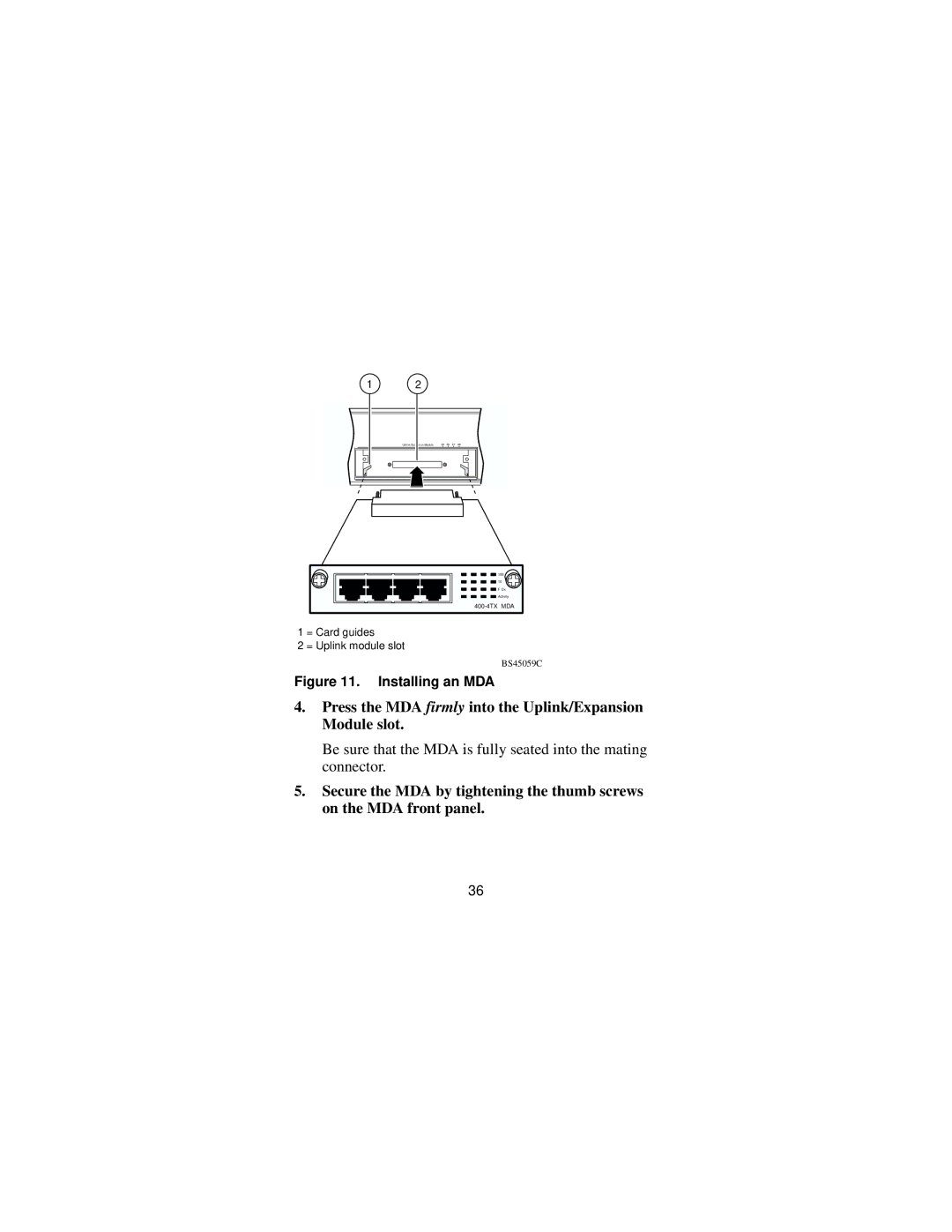
1 = Card guides
2 = Uplink module slot
BS45059C
Figure 11. Installing an MDA
4.Press the MDA firmly into the Uplink/Expansion Module slot.
Be sure that the MDA is fully seated into the mating connector.
5.Secure the MDA by tightening the thumb screws on the MDA front panel.
36