Northern Industrial Tools 142264 owner manual Operation

Models: 142264

1 13
Download 13 pages 7.55 Kb
Page 9
Image 9
OPERATION

OPERATION

1.Before making the connection to the electric control panel, check that the line voltage corresponds to that shown on the motor plate. In case of three-phase motor, check also the row or triangle connection of each phase.

2.The user must provide the electrical connection to the hoist using insulated conductors of adequate cross-section and a multiple socket fitted upstream with a suitable switch with differential magneto-thermal relay to protect form over current and indirect contacts. Also check that the ground terminal in the socket is actually connected to the grounding system.

3.The cross-section of the power supply cable must be sized according to its length.

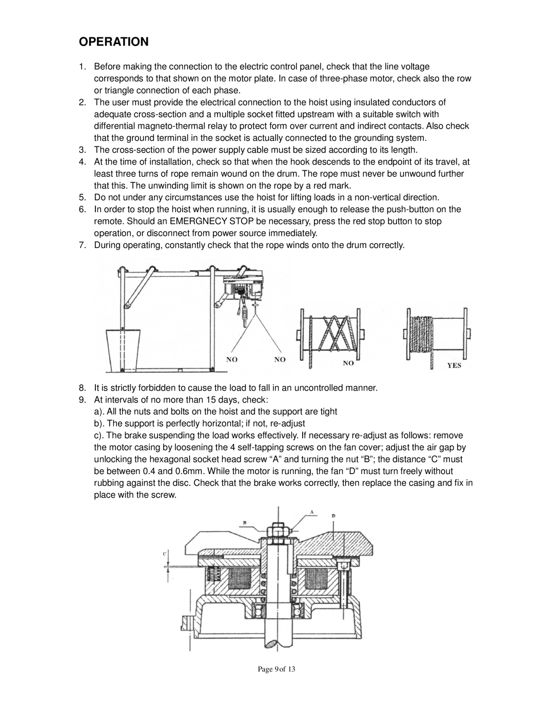
4.At the time of installation, check so that when the hook descends to the endpoint of its travel, at least three turns of rope remain wound on the drum. The rope must never be unwound further that this. The unwinding limit is shown on the rope by a red mark.

5.Do not under any circumstances use the hoist for lifting loads in a non-vertical direction.

6.In order to stop the hoist when running, it is usually enough to release the push-button on the remote. Should an EMERGNECY STOP be necessary, press the red stop button to stop operation, or disconnect from power source immediately.

7.During operating, constantly check that the rope winds onto the drum correctly.

8.It is strictly forbidden to cause the load to fall in an uncontrolled manner.

9.At intervals of no more than 15 days, check:

a). All the nuts and bolts on the hoist and the support are tight b). The support is perfectly horizontal; if not, re-adjust

c). The brake suspending the load works effectively. If necessary re-adjust as follows: remove the motor casing by loosening the 4 self-tapping screws on the fan cover; adjust the air gap by unlocking the hexagonal socket head screw “A” and turning the nut “B”; the distance “C” must be between 0.4 and 0.6mm. While the motor is running, the fan “D” must turn freely without rubbing against the disc. Check that the brake works correctly, then replace the casing and fix in place with the screw.

Page 9 of 13

Page 9
Image 9
Northern Industrial Tools 142264 owner manual Operation