DIMENSION 3 & 4 AMPLIFIERS
Rear Panel Diagram
| 15 | 7 | 8 | 9 |
|
14 |
|
|
|
|
|
| 17 |
|
| 18 | |
|
|
|
| ||
| 16 |
|
|
| |
|
|
|
|
| |
13 | 12 | 10 |
| 11 |
|
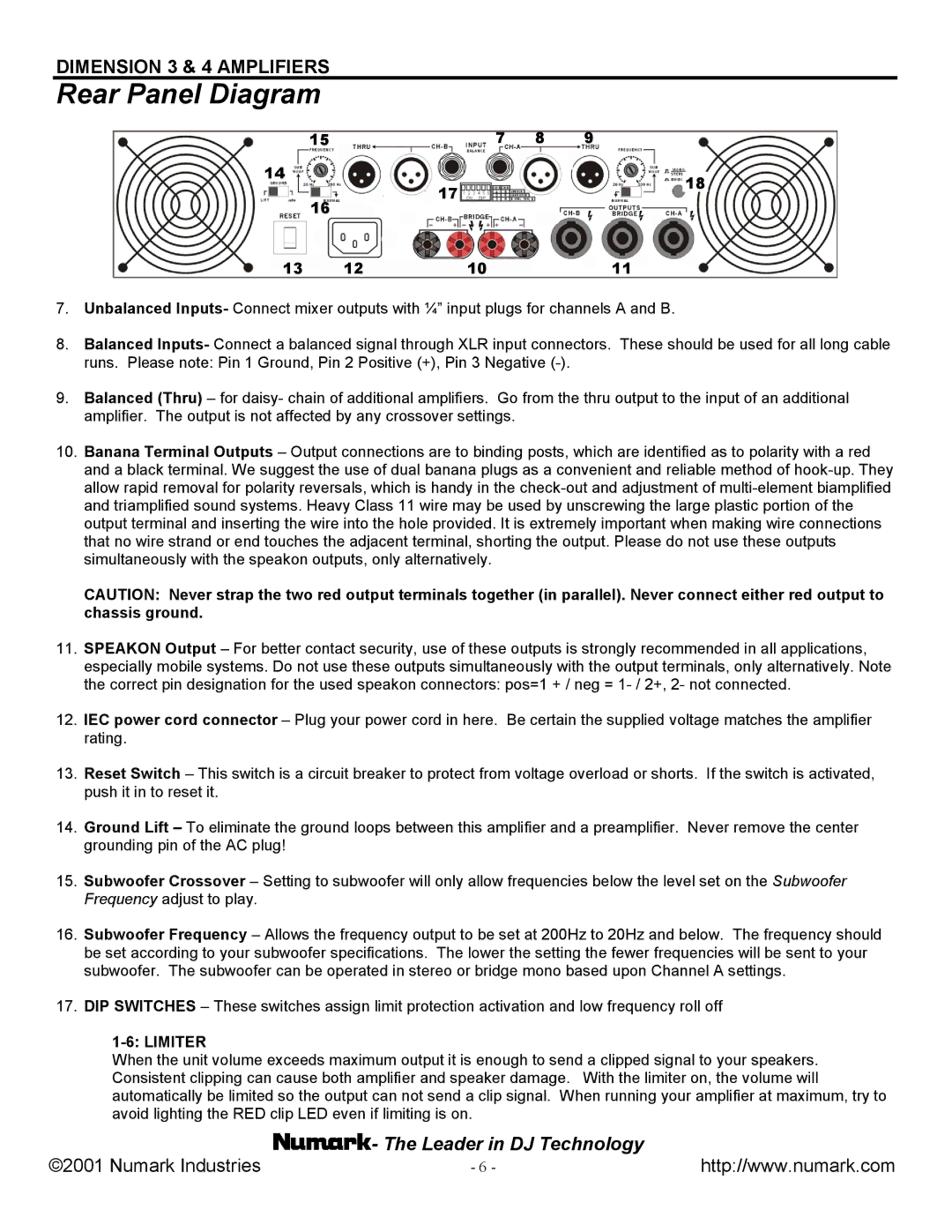
7.Unbalanced Inputs- Connect mixer outputs with ¼” input plugs for channels A and B.
8.Balanced Inputs- Connect a balanced signal through XLR input connectors. These should be used for all long cable runs. Please note: Pin 1 Ground, Pin 2 Positive (+), Pin 3 Negative
9.Balanced (Thru) – for daisy- chain of additional amplifiers. Go from the thru output to the input of an additional amplifier. The output is not affected by any crossover settings.
10.Banana Terminal Outputs – Output connections are to binding posts, which are identified as to polarity with a red and a black terminal. We suggest the use of dual banana plugs as a convenient and reliable method of
CAUTION: Never strap the two red output terminals together (in parallel). Never connect either red output to chassis ground.
11.SPEAKON Output – For better contact security, use of these outputs is strongly recommended in all applications, especially mobile systems. Do not use these outputs simultaneously with the output terminals, only alternatively. Note the correct pin designation for the used speakon connectors: pos=1 + / neg =
12.IEC power cord connector – Plug your power cord in here. Be certain the supplied voltage matches the amplifier rating.
13.Reset Switch – This switch is a circuit breaker to protect from voltage overload or shorts. If the switch is activated, push it in to reset it.
14.Ground Lift – To eliminate the ground loops between this amplifier and a preamplifier. Never remove the center grounding pin of the AC plug!
15.Subwoofer Crossover – Setting to subwoofer will only allow frequencies below the level set on the Subwoofer Frequency adjust to play.
16.Subwoofer Frequency – Allows the frequency output to be set at 200Hz to 20Hz and below. The frequency should be set according to your subwoofer specifications. The lower the setting the fewer frequencies will be sent to your subwoofer. The subwoofer can be operated in stereo or bridge mono based upon Channel A settings.
17.DIP SWITCHES – These switches assign limit protection activation and low frequency roll off
1-6: LIMITER
When the unit volume exceeds maximum output it is enough to send a clipped signal to your speakers. Consistent clipping can cause both amplifier and speaker damage. With the limiter on, the volume will automatically be limited so the output can not send a clip signal. When running your amplifier at maximum, try to avoid lighting the RED clip LED even if limiting is on.
©2001 Numark Industries | - The Leader in DJ Technology | http://www.numark.com |
- 6 - |