DM1720X
DM1720X FRONT PANEL DIAGRAM...
4 | 1 |
|
| 20 |
|
|
| 18 | 21 |
| 2 |
|
|
|
| 3 |
| 19 |
|
|
|
|
| |
5 | 6 |
| 17 |
|
| 7 |
| 15 | 16 |
| 8 |
|
|
|
|
| 10 |
|
|
| 9 | 12 | 13 | 14 |
|
|
| ||
| 11 |
|
|
|
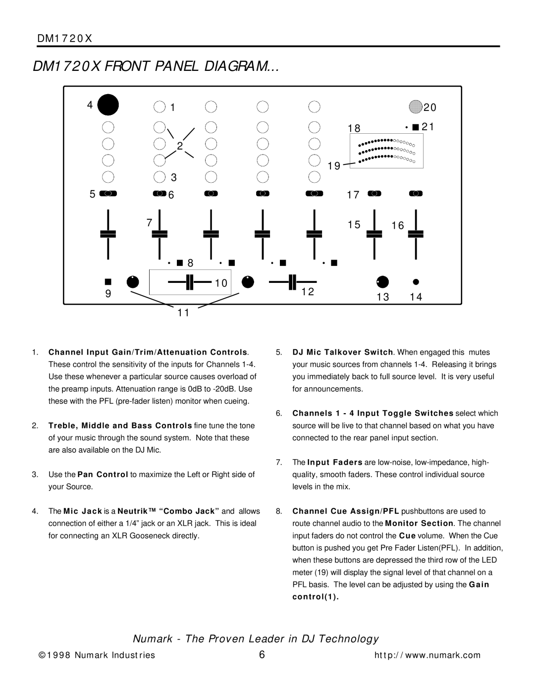
1.Channel Input Gain/Trim/Attenuation Controls. These control the sensitivity of the inputs for Channels
2.Treble, Middle and Bass Controls fine tune the tone of your music through the sound system. Note that these are also available on the DJ Mic.
3.Use the Pan Control to maximize the Left or Right side of your Source.
4.The Mic Jack is a Neutrik™ “Combo Jack” and allows connection of either a 1/4” jack or an XLR jack. This is ideal for connecting an XLR Gooseneck directly.
5.DJ Mic Talkover Switch. When engaged this mutes your music sources from channels
6.Channels 1 - 4 Input Toggle Switches select which source will be live to that channel based on what you have connected to the rear panel input section.
7.The Input Faders are
8.Channel Cue Assign/PFL pushbuttons are used to route channel audio to the Monitor Section. The channel input faders do not control the C u e volume. When the Cue button is pushed you get Pre Fader Listen(PFL). In addition, when these buttons are depressed the third row of the LED meter (19) will display the signal level of that channel on a PFL basis. The level can be adjusted by using the G a i n control(1) .
Numark - The Proven Leader in DJ Technology
©1998 Numark Industries | 6 | http://www.numark.com |