DM1720X
DM1720X REAR PANEL DIAGRAM...
|
|
|
|
|
|
|
|
|
|
|
| 1 |
|
11 | 4 | 3 | 2 | 7 | 7 | 7 | 9 | 7 | 9 | 7 | 9 | 6 | 5 |
|
10
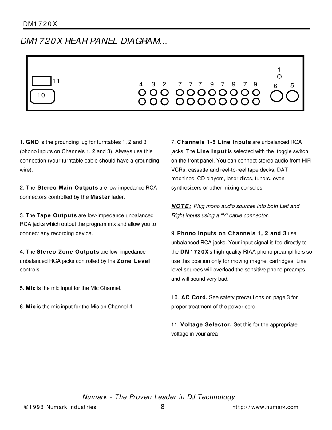
1.G N D is the grounding lug for turntables 1, 2 and 3
(phono inputs on Channels 1, 2 and 3). Always use this connection (your turntable cable should have a grounding wire).
2.The Stereo Main Outputs are
3.The Tape Outputs are
4.The Stereo Zone Outputs are
controls.
5.Mic is the mic input for the Mic Channel.
6.Mic is the mic input for the Mic on Channel 4.
7.Channels
N O T E : Plug mono audio sources into both Left and Right inputs using a “Y” cable connector.
9.Phono Inputs on Channels 1, 2 and 3 use unbalanced RCA jacks. Your input signal is fed directly to the D M 1 7 2 0 X's
10.AC Cord. See safety precautions on page 3 for proper treatment of the power cord.
11.Voltage Selector. Set this for the appropriate voltage in your area
Numark - The Proven Leader in DJ Technology
©1998 Numark Industries | 8 | http://www.numark.com |