DM2002X
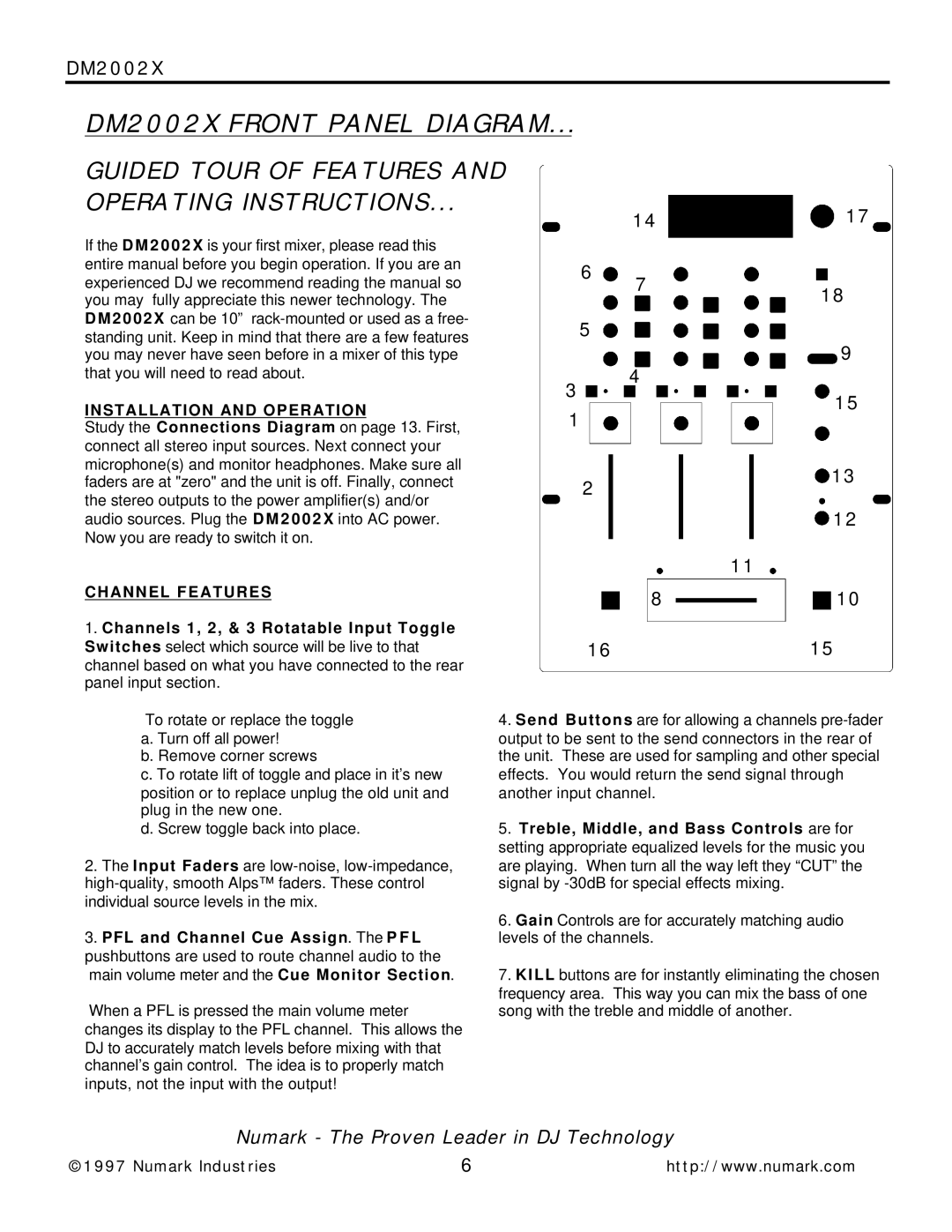
DM2002X FRONT PANEL DIAGRAM... |
| ||
GUIDED TOUR OF FEATURES AND |
|
| |
OPERATING INSTRUCTIONS... |
| 14 | |
|
| ||
If the D M 2 0 0 2 X is your first mixer, please read this |
|
| |
entire manual before you begin operation. If you are an | 6 | 7 | |
experienced DJ we recommend reading the manual so | |||
| |||
you may fully appreciate this newer technology. The |
|
| |
D M 2 0 0 2 X can be 10” | 5 |
| |
standing unit. Keep in mind that there are a few features |
| ||
|
| ||
you may never have seen before in a mixer of this type |
|
| |
that you will need to read about. | 3 | 4 | |
INSTALLATION AND OPERATION |
| ||
1 |
| ||
Study the Connections Diagram on page 13. First, |
| ||
|
| ||
connect all stereo input sources. Next connect your |
|
| |
microphone(s) and monitor headphones. Make sure all |
|
| |
faders are at "zero" and the unit is off. Finally, connect | 2 |
| |
the stereo outputs to the power amplifier(s) and/or |
| ||
|
| ||
audio sources. Plug the D M 2 0 0 2 X into AC power. |
|
| |
Now you are ready to switch it on. |
|
| |
CHANNEL FEATURES |
| 8 | |
1. Channels 1, 2, & 3 Rotatable Input Toggle |
|
| |
Switches select which source will be live to that | 16 |
| |
channel based on what you have connected to the rear |
|
| |
panel input section.
17
18
9
15
13
12
11
10
15
To rotate or replace the toggle a. Turn off all power!
b. Remove corner screws
c. To rotate lift of toggle and place in it’s new position or to replace unplug the old unit and plug in the new one.
d. Screw toggle back into place.
2.The Input Faders are
3.PFL and Channel Cue Assign. The P F L pushbuttons are used to route channel audio to the main volume meter and the Cue Monitor Section.
When a PFL is pressed the main volume meter changes its display to the PFL channel. This allows the DJ to accurately match levels before mixing with that channel’s gain control. The idea is to properly match inputs, not the input with the output!
4.Send Buttons are for allowing a channels
5.Treble, Middle, and Bass Controls are for setting appropriate equalized levels for the music you are playing. When turn all the way left they “CUT” the signal by
6.Gain Controls are for accurately matching audio levels of the channels.
7.KILL buttons are for instantly eliminating the chosen frequency area. This way you can mix the bass of one song with the treble and middle of another.
Numark - The Proven Leader in DJ Technology
©1997 Numark Industries | 6 | http://www.numark.com |