REAR PANEL FEATURES
![]()
![]()
![]() 3
3 ![]()
![]()
![]()
![]()
![]()
![]()
![]() 2
2![]()
![]()
![]()
1
10 | 11 12 | 6 | 4 | 4 | 7 | 9 | 8 |
|
|
|
|
|
|
| |
|
| 5 |
|
| 5 |
|
|
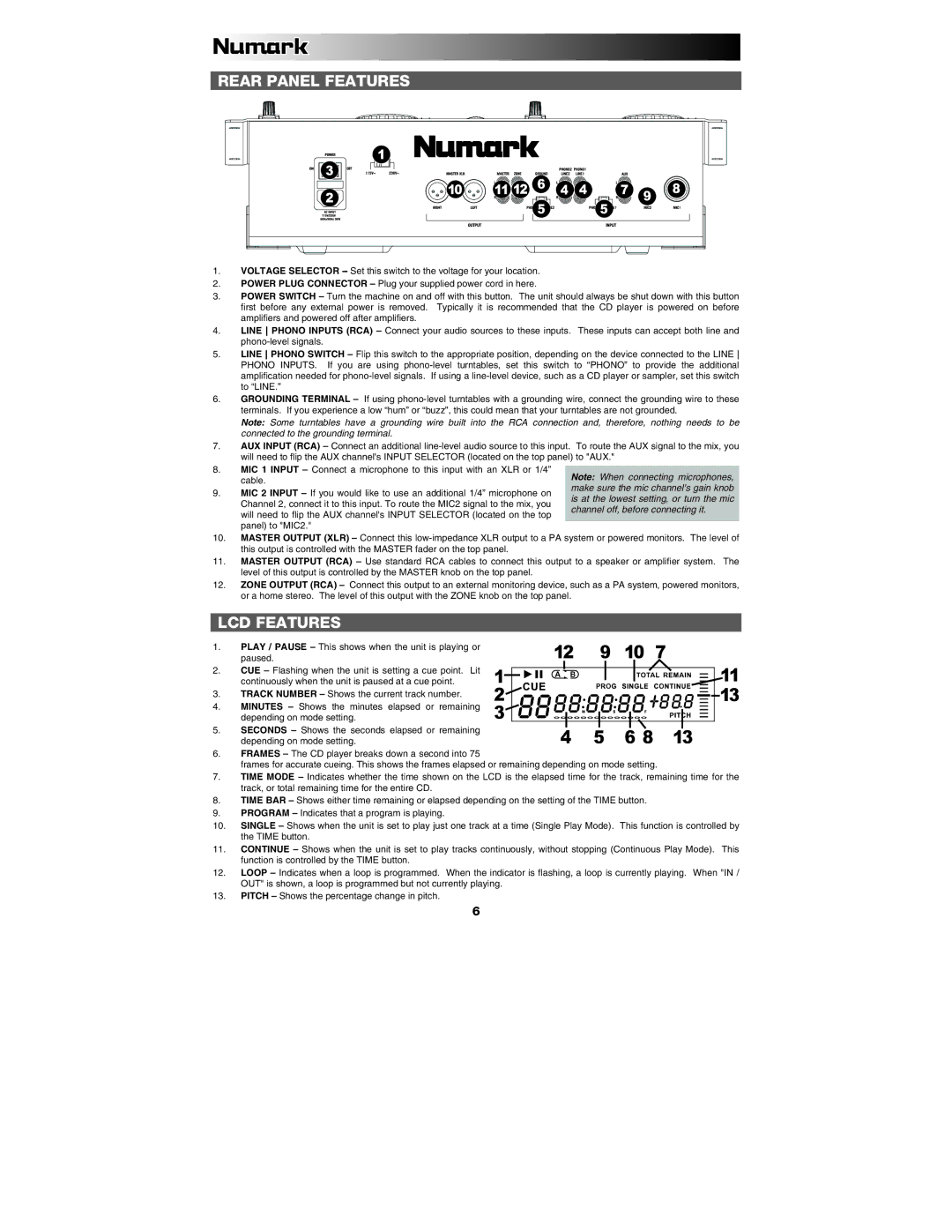
1.VOLTAGE SELECTOR
2.POWER PLUG CONNECTOR – Plug your supplied power cord in here.
3.POWER SWITCH – Turn the machine on and off with this button. The unit should always be shut down with this button first before any external power is removed. Typically it is recommended that the CD player is powered on before amplifiers and powered off after amplifiers.
4.LINE PHONO INPUTS (RCA) – Connect your audio sources to these inputs. These inputs can accept both line and
5.LINE PHONO SWITCH – Flip this switch to the appropriate position, depending on the device connected to the LINE PHONO INPUTS. If you are using
6.GROUNDING TERMINAL – If using
Note: Some turntables have a grounding wire built into the RCA connection and, therefore, nothing needs to be connected to the grounding terminal.
7.AUX INPUT (RCA) – Connect an additional
8.MIC 1 INPUT – Connect a microphone to this input with an XLR or 1/4” cable.
9.MIC 2 INPUT – If you would like to use an additional 1/4” microphone on Channel 2, connect it to this input. To route the MIC2 signal to the mix, you will need to flip the AUX channel's INPUT SELECTOR (located on the top panel) to "MIC2."
Note: When connecting microphones, make sure the mic channel's gain knob is at the lowest setting, or turn the mic channel off, before connecting it.
10.MASTER OUTPUT (XLR) – Connect this
11.MASTER OUTPUT (RCA) – Use standard RCA cables to connect this output to a speaker or amplifier system. The level of this output is controlled by the MASTER knob on the top panel.
12.ZONE OUTPUT (RCA) – Connect this output to an external monitoring device, such as a PA system, powered monitors, or a home stereo. The level of this output with the ZONE knob on the top panel.
LCD FEATURES
1.PLAY / PAUSE – This shows when the unit is playing or paused.
2.CUE – Flashing when the unit is setting a cue point. Lit continuously when the unit is paused at a cue point.
3.TRACK NUMBER – Shows the current track number.
4.MINUTES – Shows the minutes elapsed or remaining depending on mode setting.
5.SECONDS – Shows the seconds elapsed or remaining depending on mode setting.
12 | 9 | 10 | 7 |
|
|
|
|
|
|
|
|
| |||||||||||||
1 |
|
|
|
|
|
|
|
|
|
|
|
|
|
|
|
|
|
|
|
|
|
|
|
| 11 |
2 |
|
|
|
|
|
|
|
|
|
|
|
|
|
|
|
|
|
|
|
|
|
|
| 13 | |
|
|
|
|
|
|
|
|
|
|
|
|
|
|
|
|
|
|
|
|
|
|
| |||
|
|
|
|
|
|
|
|
|
|
|
|
|
|
|
|
|
|
|
|
|
|
| |||
3 |
|
|
|
|
|
|
|
|
|
|
|
|
|
|
|
|
|
|
|
|
|
|
|
| |
|
|
|
|
|
|
|
|
|
|
|
|
|
|
|
|
|
|
|
|
|
|
|
| ||
|
|
|
|
|
|
|
|
|
|
|
|
| |||||||||||||
4 | 5 |
| 6 8 | 13 |
|
|
|
| |||||||||||||||||
6.FRAMES – The CD player breaks down a second into 75
frames for accurate cueing. This shows the frames elapsed or remaining depending on mode setting.
7.TIME MODE – Indicates whether the time shown on the LCD is the elapsed time for the track, remaining time for the track, or total remaining time for the entire CD.
8.TIME BAR – Shows either time remaining or elapsed depending on the setting of the TIME button.
9.PROGRAM – Indicates that a program is playing.
10.SINGLE – Shows when the unit is set to play just one track at a time (Single Play Mode). This function is controlled by the TIME button.
11.CONTINUE – Shows when the unit is set to play tracks continuously, without stopping (Continuous Play Mode). This function is controlled by the TIME button.
12.LOOP – Indicates when a loop is programmed. When the indicator is flashing, a loop is currently playing. When "IN / OUT" is shown, a loop is programmed but not currently playing.
13.PITCH – Shows the percentage change in pitch.
6