INSTALLATION & OPERATING INSTRUCTIONS READ & SAVE THESE INSTRUCTIONS!
Wireless Chimes
MODELS: LA-228WH or LA-245MR
•For use with the
Congratulations on your purchase of a NuTone wireless chime. The chime operates by a radio frequency signal transmitted by the pushbutton and received by the chime. The pushbutton/transmitter is mounted at the door. The receiver may be located anywhere in your home within 100 feet (30 meters) of the pushbutton. The pushbutton/transmitter can be programmed to sound one of three chime sounds. This feature allows up to three pushbuttons to generate three different chime sounds.
MOUNTING THE PUSHBUTTON TRANSMITTER
TO OPEN COVER “PUSH”
FIGURE 1
SCREW HOLE FOR WALL
MOUNTING
SCREW HOLE FOR WALL | FIGURE 2 |
MOUNTING |
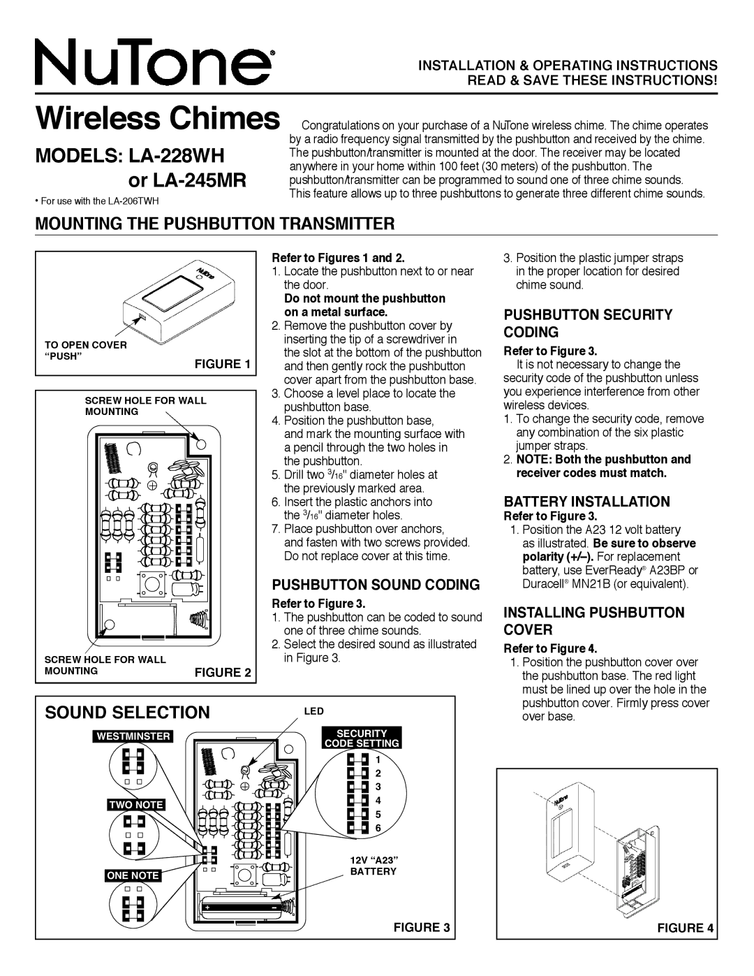
SOUND SELECTION
Refer to Figures 1 and 2.
1.Locate the pushbutton next to or near the door.
Do not mount the pushbutton on a metal surface.
2.Remove the pushbutton cover by inserting the tip of a screwdriver in the slot at the bottom of the pushbutton and then gently rock the pushbutton cover apart from the pushbutton base.
3.Choose a level place to locate the pushbutton base.
4.Position the pushbutton base,
and mark the mounting surface with a pencil through the two holes in the pushbutton.
5.Drill two 3/16" diameter holes at the previously marked area.
6.Insert the plastic anchors into the 3/16" diameter holes.
7.Place pushbutton over anchors, and fasten with two screws provided. Do not replace cover at this time.
PUSHBUTTON SOUND CODING
Refer to Figure 3.
1.The pushbutton can be coded to sound one of three chime sounds.
2.Select the desired sound as illustrated in Figure 3.
LED
3.Position the plastic jumper straps in the proper location for desired chime sound.
PUSHBUTTON SECURITY CODING
Refer to Figure 3.
It is not necessary to change the security code of the pushbutton unless you experience interference from other wireless devices.
1.To change the security code, remove any combination of the six plastic jumper straps.
2.NOTE: Both the pushbutton and receiver codes must match.
BATTERY INSTALLATION
Refer to Figure 3.
1.Position the A23 12 volt battery as illustrated. Be sure to observe polarity
INSTALLING PUSHBUTTON COVER
Refer to Figure 4.
1.Position the pushbutton cover over the pushbutton base. The red light must be lined up over the hole in the pushbutton cover. Firmly press cover over base.
WESTMINSTER
TWO NOTE
ONE NOTE
+ | – |
SECURITY
CODE SETTING
1
2
3
4
5
6
12V “A23”
BATTERY
FIGURE 3
FIGURE 4